



 Multiple industries nationwide (electroplating and surface treatment / PCB circu
 Pilot to engineering scale (100 m³/d to 200 m³/d per train, centralized treatmen
Alkaline Precipitation for Heavy Metal Wastewater: pH Falls Within the "Precipitation Range," So Why Is the Effluent Still Non-Compliant?
In the treatment of heavy metal-containing wastewater, the most discussed topics are "is the dosage sufficient" and "which chemical to choose." But when the workshop outlet repeatedly exceeds the limit, the cause is rarely the dosage. What truly causes a precipitation system to fail comes down to three things that almost no one examines side by side: which table and which discharge outlet the number you need to meet belongs to; whether the "optimal precipitation pH" you looked up is a broad range or a narrow window; and whether the complexing agents in the water have locked the metals in solution.
I. First, locate it: precipitation occupies only one cell in the entire chain, and the outcome is determined before it
The "Technical Specifications for Electroplating Wastewater Treatment Engineering" (HJ 2002—2010) has very direct requirements for the process sequence: wastewater should be collected and treated separately according to its properties, chromium-containing wastewater and nickel-containing wastewater should be collected and treated separately and must not be mixed with other wastewater; only after hexavalent chromium is reduced to trivalent chromium may it be mixed with other metal wastewater for treatment. This is not a recommendation; it locks "whether the limit can be met" in advance at the piping level.
A complete heavy metal wastewater treatment chain typically looks like this: segregated collection → separate reduction of chromium-containing wastewater (reduction of Cr⁶⁺ to Cr³⁺ under acidic conditions) → decomplexation (for wastewater containing cyanide, nickel, or complexing agents) → neutralization and precipitation → coagulation and flocculation → precipitation separation (inclined tube/inclined plate or high-efficiency sedimentation tank) → filtration and advanced polishing (sand filtration, heavy metal capture agents, or ion exchange).
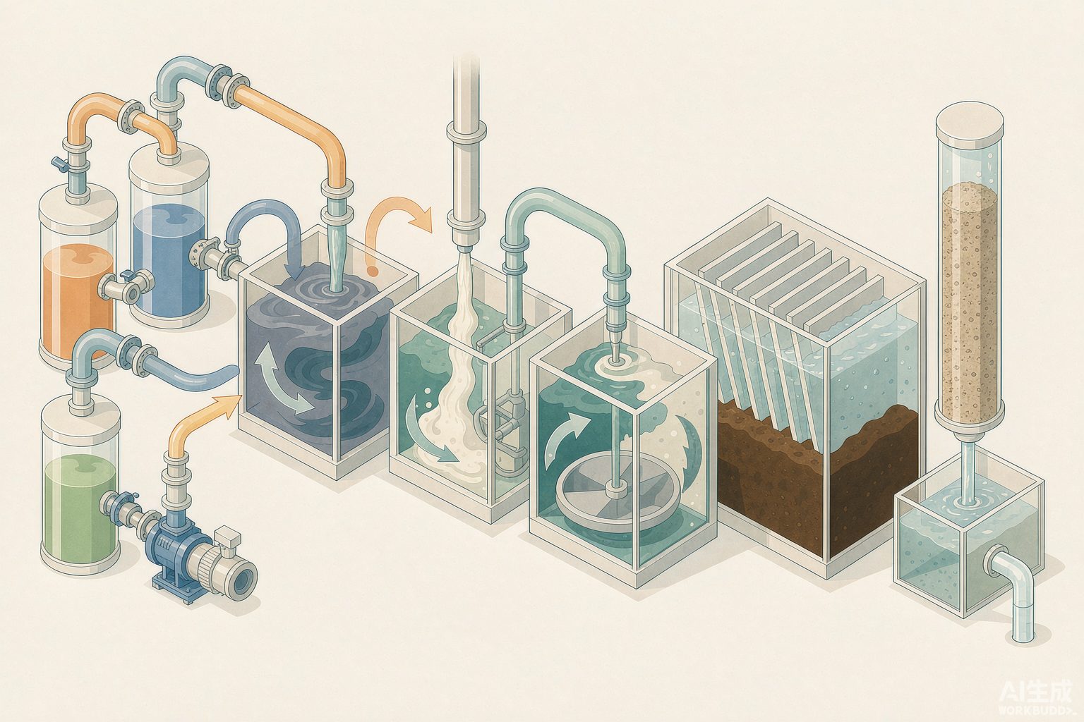
Laying out this chain reveals a counterintuitive fact: the sedimentation tank itself has almost no design difficulty; the difficulty lies entirely in the two actions before it—separating the water that should not be mixed, and opening up the complexing agents that lock in the metals. The three criteria discussed in the following three sections all fall on these two actions.
II. Criterion One: Which table and which discharge outlet the number you need to meet belongs to
The electroplating and surface treatment industry implements GB 21900—2008 "Electroplating Pollutant Discharge Standard," but within the same standard there are two sets of concentration limits, and there is more than one monitoring location: Table 2 applies to existing enterprises and new enterprises, while Table 3 is the special discharge limit for water pollutants, applicable to areas with high land development density, small water environmental capacity, and fragile ecological environment, with the specific scope and timing of implementation prescribed by the ecological and environmental authorities under the State Council or the provincial-level people's government.
| Pollutant Item | Table 2 (Wastewater Discharge Outlet of Workshop or Production Facility) | Table 3 (Special Emission Limits, Workshop Outlet) | Tightening Factor |
|---|---|---|---|
| Total Chromium | 1.0 mg/L | 0.5 mg/L | 2 times |
| Hexavalent Chromium | 0.2 mg/L | 0.1 mg/L | 2 times |
| Total Nickel | 0.5 mg/L | 0.1 mg/L | 5 times |
| Total Cadmium | 0.05 mg/L | 0.01 mg/L | 5 times |
| Total Silver / Total Lead | 0.3 / 0.2 mg/L | 0.1 / 0.1 mg/L | 3 times / 2 times |
| Total Mercury | 0.01 mg/L | 0.005 mg/L | 2 times |
| Total Copper / Total Zinc (Enterprise Wastewater General Discharge Outlet) | 0.5 / 1.5 mg/L | 0.3 / 1.0 mg/L | 1.67 times / 1.5 times |
| Baseline Wastewater Discharge per Unit Product (Multilayer Plating / Single-layer Plating) | 500 / 200 L·m⁻² | 250 / 100 L·m⁻² | 2 times |
The most easily overlooked item in this table is the "discharge volume" in the last row. Article 4.1.6 of GB 21900—2008 explicitly states that the concentration limits apply only when the actual wastewater discharge per unit product does not exceed the baseline discharge volume; if the actual discharge volume exceeds the baseline discharge volume, the measured concentration must be converted into the discharge concentration based on the baseline water volume, and compliance must be judged using the converted value. In other words, dilution not only fails to solve the problem, but is also penalized in reverse through the conversion formula.
A stricter rule comes from an older and more fundamental standard. Article 4.2.1.1 of GB 8978—1996 "Integrated Wastewater Discharge Standard" stipulates that Class I pollutants regardless of industry, regardless of wastewater discharge method, and regardless of the functional category of the receiving water body, shall all be sampled at the workshop or workshop treatment facility discharge outlet, and their maximum permissible discharge concentrations must meet the standard requirements. The tailings dam outlet of the mining industry shall not be regarded as a workshop discharge outlet. There are 13 types of Class I pollutants in total, among which the metal category includes total mercury, alkyl mercury, total cadmium, total chromium, hexavalent chromium, total arsenic, total lead, total nickel, total beryllium, and total silver. The reply letter issued by the Ministry of Ecology and Environment on 2016 年 1 月 further confirmed that the five major heavy metals—lead, mercury, chromium, cadmium, and the metalloid arsenic—shall be monitored at the workshop or workshop treatment facility discharge outlet as Class I pollutants and their discharge amounts calculated accordingly.
In other words, "nickel-containing wastewater separately collected, separately treated, and separately discharged" is a pipeline requirement that must hold physically. Merging nickel-containing rinse water into the central station for unified precipitation, even if the final outlet data looks good, does not constitute compliance—this is explicitly listed as dilution discharge.
III. Caliber 2: Is the "optimal precipitation pH" a range or a window?
This is the most easily overlooked point in the entire article. When we searched both Chinese and English materials for the "optimal precipitation pH of various metal hydroxides," what we obtained was not one set of numbers, but two sets of numbers with completely different calibers: domestic technical materials give a wide range (for example, nickel ">9.5," "9~12"), while foreign equipment suppliers and engineering guidelines give a narrow window (for example, nickel 10.0~11.0).
| Metal | Domestic Data Range (Wide Range) | Engineering Guideline Range (Narrow Window) | Re-dissolution Risk |
|---|---|---|---|
| Cu²⁺ | >8;7~12 | 7.0~8.5;8.5~9.5 | Too high, forms copper-ammonia complex |
| Ni²⁺ | >9.5;9~12 | 10.0~11.0;9.5~10.5 | In the presence of ammonia, >10.5 re-dissolves |
| Zn²⁺ | 9~10 | 8.5~10.0 | >10.5 forms [Zn(OH)₄]²⁻ and re-dissolves |
| Cr³⁺ | 8~9 | 7.5~8.5;8~9.5 | Easily soluble in both strong acid and strong alkali |
| Pb²⁺ | 9~9.5 | 8.5~10.0 | Limited increase in solubility at too high pH |
| Cd²⁺ | >10.5;11~12 | 10.0~11.0;10.5~11.5 | >11.5 slight re-dissolution |
| Fe³⁺ | 6~12 | 6~9 | Also easily precipitates at low pH, widest window |
| Al³⁺ | 5.5~8 | 5.5~7.5 | Pronounced amphoteric behavior, dissolves at >9 |
Both sets of numbers are actually correct; they refer to two different things. The wide range answers "can flocs be seen," while the narrow window answers "can the limit be met." The solubility of metal hydroxides follows a bowl-shaped curve with pH: at the rim of the bowl, solubility is so high that precipitation simply cannot occur; on the walls of the bowl, turbidity becomes visible to the naked eye; only within the 1~1.5 pH units at the bottom of the bowl can the effluent concentration possibly reach the order of 0.1 mg/L.
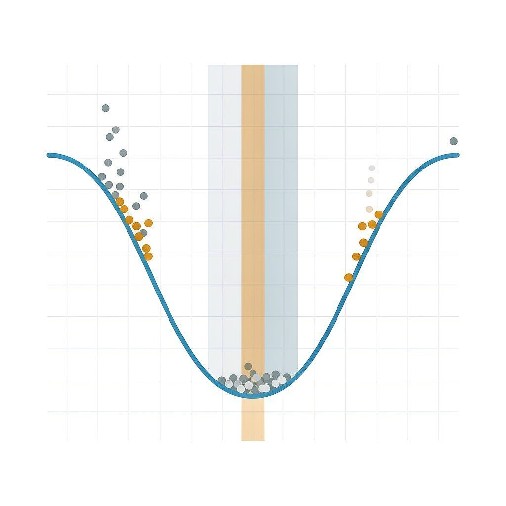
Applying this distinction to actual wastewater immediately reveals how acute the contradiction is: the narrow window for a single wastewater stream can be hit, but the narrow window for mixed wastewater cannot. Nickel-containing wastewater must be brought down to 10.0–11.0, while zinc-containing wastewater begins to re-dissolve as [Zn(OH)₄]²⁻ once it exceeds 10.5. These two conditions cannot be satisfied simultaneously in the same tank. In engineering practice, only a compromise value can be chosen (commonly 9.0–9.5), and the precise meaning of "compromise" in this context is: there is always one element that cannot achieve its minimum solubility.
IV. Approach Three: When Complexing Agents Are Present, the pH Knob Fails
All the preceding discussion about pH is based on the premise that "metals exist as free hydrated ions." Once wastewater contains ligands such as cyanide (CN⁻), ammonia (NH₃), EDTA, citric acid, or pyrophosphate, this premise no longer holds—they will form soluble complexes with metals, and the hydroxide precipitation method can hardly precipitate and separate them, or may not generate precipitation at all. This is also why the same process runs well in Workshop A but immediately fails when moved to Workshop B.
A study on comprehensive electroplating wastewater treatment at a large electroplating industrial park in Shenzhen quantified this difficulty very concretely: copper and nickel in acid-base comprehensive wastewater form very stable complexes, and traditional hydroxide and sulfide precipitation methods cannot treat them to meet standards; acidification–oxidation decomplexation must first be used to break the coordination bonds so that the metals change from complexed form to free form, and then a precipitation process combining sulfide and hydroxide is used for removal. Its optimized decomplexation conditions were bleach water (sodium hypochlorite) dosage 1.2 mL/L, pH 2.3, reaction 2.0 h; the optimal precipitation conditions after decomplexation were coarse adjustment with lime plus fine adjustment with alkali liquor to about pH 10.0, and sodium sulfide dosage 600 mg/L. The study also found a very practical conclusion: after adding air flotation oil removal pretreatment before the entire process, the sodium sulfide dosage can be reduced to 200 mg/L—with the same target and the same water quality, adding one upstream step reduced the main chemical dosage by two-thirds.
There are three engineering routes for decomplexation, and which one to choose depends on what the complexing agent is:
| Complex Breaking Route | Applicable Complexing Agents | Typical Conditions | Cost |
|---|---|---|---|
| Oxidative Complex Breaking | Cyanide, EDTA, Citric Acid, Organophosphonates | Sodium Hypochlorite (acidic or alkaline), Fenton, Ozonation, Electrolytic Anodic Oxidation | High chemical cost; may introduce residual chlorine and COD |
| Acidification Decomplexation | Weak Complexation (Aminocarboxylic Acid Type) | Acidify to pH 2~3 to disrupt the coordination equilibrium, then neutralize | High acid and alkali consumption; ineffective for strong complexation |
| Displacement Decomplexation | Displacement by high-concentration competing ions such as calcium and ferrous iron | Dose Fe²⁺ / Ca²⁺ to occupy the ligands | Significant increase in sludge volume |
| Chelating Capture (DTC Type) | Directly penetrates the complex bond and then chelates | Dosage is 2~5 times the total heavy metals, pH 4~12, reaction 15~30 min | Highest unit chemical cost; overdose causes colloid restabilization |
The fourth route is one that has been increasingly used in engineering over the past decade: heavy metal capture agents represented by dithiocarbamates (DTC). The sulfur atom in the molecule is a soft base, forming five- or six-membered ring chelates with soft acid-type metals such as copper, nickel, and cadmium. Its bond energy is far higher than the ionic bond of hydroxide precipitation, so it is claimed that complexed metals can be directly captured under conditions from weakly acidic to weakly alkaline and with high calcium and magnesium hardness. Its value does exist—measured data from multiple projects show that for targets such as EDTA-Ni that conventional processes cannot handle, DTC can reduce effluent nickel to below 0.05 mg/L (see the ledger in the next section). But its boundaries are equally clear: overdosing leads to colloid restabilization and elevated effluent COD. Industry materials repeatedly emphasize that "more is not always better," and determining the dosage coefficient through laboratory bench tests is an essential step.
V. Calculating the Reagent Account Yourself: Three Repeatedly Cited "Theoretical Dosage Ratios"
1. Sodium Bisulfite Reduction of Hexavalent Chromium: The Textbook's "Theoretical 4:1" Is Actually 3.0:1 According to the Reaction Equation
The reduction and precipitation of chromium-containing wastewater is the most standardized process, and almost every textbook gives the line "theoretical reducing agent dosage (weight ratio): sodium bisulfite : hexavalent chromium = 4:1." This figure is worth verifying yourself. The reduction reaction equation is:
According to the equation, each 2 mol of hexavalent chromium (calculated as Cr, 2×52.00 = 104.0 g) requires 3 mol NaHSO₃ (3×104.06 = 312.2 g);
m(NaHSO₃)/m(Cr⁶⁺) = 312.2 ÷ 104.0 = 3.00.
In other words, the 4:1 referred to as the "theoretical dosage" already includes a margin of approximately 33%. Meanwhile, engineering documents generally state "actual dosage of 4~5:1 to ensure complete reaction." Combining the two, the sodium bisulfite actually dosed into the tank may be 1.3~1.7 times the stoichiometric amount. This is not an error—it is an industry habit of mixing "the safety factor number" and "the stoichiometric number" in the same sentence. The same conversion applies to other reducing agents: sodium metabisulfite (Na₂S₂O₅) is written as 3:1 in the literature, which converts to 2.74:1; sodium sulfite (Na₂SO₃) is written as 4:1, which converts to 3.64:1—the three reagents have different "theoretical ratio" numbers, but the true stoichiometry is all around 1.5 mol of tetravalent sulfur per mol of hexavalent chromium.
There is another discrepancy in the endpoint control of the reduction process: some commercial materials state "online ORP controlled below −100 mV to ensure the reaction endpoint," while some engineering suppliers state "ORP −250~−300 mV" [to be verified]. The two differ by more than a factor of two, and the direction differs from the common oxidizing potential range. In engineering, one should not copy a design based on any single ORP number, but should rely on synchronized online hexavalent chromium monitoring (or diphenylcarbazide colorimetric) measured endpoint, with ORP only as a trend reference.
2. Sulfide Precipitation: The Dosage Ratio Is Not 1:1, and Exceeding 1.5:1 Will Cause Problems
The solubility of metal sulfides is generally several orders of magnitude lower than that of the corresponding hydroxides (see table below), so sulfide precipitation can reach low concentration ranges that hydroxide precipitation cannot. However, its dosage has a clear ceiling. A study in ChemEngineering 2020 年 on sulfide precipitation with Na₂S and HS⁻ solutions provides a set of theoretical values and precipitation pH:
| Metal | Sulfide log Ksp | Hydroxide log Ksp | Gap (orders of magnitude) | pH Required for Sulfide Precipitation |
|---|---|---|---|---|
| Hg | −52.2 | −25.4 | 26.8 | — |
| Cu | −35.9 | −19.8 | 16.1 | 2.5 (alternative basis 1.5~2) |
| Cd | −28.9 | −14.3 | 14.6 | 4 |
| Pb | −28.1 | −19.9 | 8.2 | — |
| Zn | −24.5 | −16.1 | 8.4 | 5.5 (alternative basis 2.2~4.1) |
| Ni | −21.0 | −15.3 | 5.7 | 7.5 (alternative basis 5.6~8.6) |
| Fe(II) | −18.8 | −16.3 | 2.5 | 5~7.4 |
| Mn | −13.3 | −12.7 | 0.6 | 7.7~9.7 |
The most noteworthy row in the table is the last one: the sulfide solubility of manganese is only 0.6 orders of magnitude lower than its hydroxide—sulfide precipitation offers almost no advantage for manganese, which is why many attempts to switch manganese-containing wastewater to sulfide precipitation end up ineffective. It can also be seen that sulfide precipitation offers the greatest advantage for copper, cadmium, and mercury (more than 10 orders of magnitude), while the advantage is markedly weaker for nickel, iron, and manganese. This is consistent with the engineering experience that "sulfide precipitation is specifically suited for low-concentration copper and cadmium."
In terms of dosage, a study on metal pickling wastewater based on a three-factor, four-level orthogonal experiment provides a usable window: the influence weights of three factors—reaction time (30~45 min), sulfidizing agent dosage (1.1~1.3 times the theoretical value), and stirring intensity (80~120 rpm)—on treatment efficiency are 45%, 35%, and 20%, respectively; when the sulfidizing agent is overdosed beyond a 1.5:1 molar ratio, the residual sulfide ion concentration will rise above 5 mg/L, and the optimized range is to control the total amount of metal ions and sulfide ions at a ratio of 1.2:1.
3. Lime-ferric salt process for arsenic removal: the same Fe/As molar ratio has four different formulations in the literature
Arsenic, as a metalloid, also belongs to the first category of pollutants, and acid wastewater from the smelting and sulfuric acid industries is the main source. Arsenic removal process routes are highly concentrated on the lime-ferric salt process, and its core parameter, the Fe/As molar ratio, appears in the literature in four formulations with an extremely wide range:
| Fe/As Molar Ratio | Supporting Conditions | Arsenic Removal Performance | Source Basis |
|---|---|---|---|
| 1.05 | pH 5.5, H₂O₂ oxidation, 70℃ | As 10 034 → 900 mg/L (81.4%), then reduced to 18.84 mg/L via ion exchange, total arsenic removal rate 99.5% | Cascade Arsenic Removal from Copper Smelting Waste Acid (JOM 2025) |
| 3 | Lime–ferrous sulfate two-stage precipitation, effluent pH around 8 | Removal rate approximately 99.5% | Improved Scheme for Arsenic-Containing Wastewater |
| 4.5 | H₂O₂/As = 1.5, endpoint pH 8, seed ratio 1:1, 3 h | Effluent As 0.12 mg/L (limit 0.5), arsenic removal rate approaching 100%, slag TCLP 2.25 mg/L (limit 3) | Industrial Application of High-Arsenic Waste Acid (BGRIMM Technology Group, Nonferrous Metals (Smelting Section) 2024) |
| 5~10 | Reaction liquid pH 7~8, partial reflux of sediment as crystal nuclei | Cu, Pb, Zn, As removal rates all stably >99% | Process Review and Engineering Practice of Lime–Iron Salt Method |
The difference among the four approaches is not about "which is correct," but about which stage they belong to and what level they are meant to treat down to. 1.05 appears in the first-stage rough removal (bringing As from the tens of thousands mg/L level down to the thousands mg/L level), with the purpose of first recovering valuable metals and reducing the downstream load; 4.5 and 5~10 appear in the deep arsenic removal stage, with the goal of pressing residual arsenic down to 0.5 mg/L or even below 0.1 mg/L. What is truly worth replicating in engineering is not the ratio figures, but the structure of "first stage it, then set a target for each stage": for high-arsenic waste acid, first use lime at pH 1.2, add gypsum seed crystals, and react for 2 h to preferentially produce qualified gypsum product, then enter the oxidation and deep arsenic removal stage—separating gypsum from arsenic slag is the key action for slag volume control.
VI. Real Ledger: Engineering and Experimental Data from 11 Verifiable Sources
The table below juxtaposes the key data covered in this article. It should be noted that: rows marked "Commercial Technical Materials" come from publicly available cases of equipment suppliers and chemical suppliers, have not undergone peer review, and the dosage and effluent data may reflect promotional framing; please use them as directional references and verify through bench-scale tests; rows marked with journal names come from publicly available literature.
| Wastewater Type and Scale | Process and Key Parameters | Influent/Effluent and Performance | Source |
|---|---|---|---|
| A large electroplating industrial park in Shenzhen Comprehensive electroplating wastewater | NaHSO₃ dosage 1.4 times theoretical amount, pH 1.8, 15 min reduction; Cr³⁺ coarsely adjusted with lime + finely adjusted with alkali to pH≈9.0; complexed copper and nickel first broken by bleaching (1.2 mL/L, pH 2.3, 2 h), then lime-adjusted to pH 10.0 + Na₂S 600 mg/L | Traditional hydroxide/sulfide precipitation "cannot treat copper-nickel complexes to compliance"; after pre-positioned air flotation for oil removal, Na₂S can be reduced to 200 mg/L | Dissertation (Research on Comprehensive Electroplating Wastewater Treatment Technology) |
| Fine chemical wastewater 100 m³/d | Chemical precipitation pretreatment + Fenton Oxidation / coagulation air flotation / Hydrolysis Acidification / Aerobic aeration | Total copper removal >99%, total nickel >80%, COD >94%, TP >90%, meeting local discharge-to-sewer standards | China Water & Wastewater 2018, 34(8) |
| High-arsenic waste acid Industrial application at a mining and metallurgy enterprise | Stage 1 pH 1.2, gypsum seed 1:1, 2 h produces gypsum; Stage 2 H₂O₂/As = 1.5, endpoint pH 8, Fe/As = 4.5, 3 h | After arsenic removal, liquid As 0.12 mg/L (limit 0.5), arsenic removal rate approaching 100%; arsenic removal residue TCLP 2.25 mg/L (limit 3) | Nonferrous Metals (Smelting Section) 2024 |
| Arsenic-containing waste acid from copper smelting | Lime–iron salt + ion exchange cascade: Fe/As = 1.05, pH 5.5, 70℃; resin 8:1, 20℃, 8 h adsorption | As 10 034 → 900 mg/L (81.4%) → 18.84 mg/L, total arsenic removal rate 99.5% | JOM 2025, 77: 5632 |
| Arsenic-containing acidic wastewater from copper smelting Engineering practice | Lime–iron salt process, Fe/As molar ratio 5~10, reaction pH 7~8, partial reflux of sediment as crystal nuclei | Removal rates of Cu, Pb, Zn, and As all stably >99%; As in neutralization sludge exists as pentavalent arsenate, leaching <5 mg/L, safe for stockpiling | Review of lime–iron salt process |
| Hardware pickling wastewater Orthogonal experiment | pH 8.5~9.0, Na₂S dosage 1.1~1.3 times theoretical value, reaction 30~45 min, stirring 80~120 rpm | Removal rates of Cu/Ni/Zn all >98%, effluent Cu ≤0.3, Ni ≤0.1, Zn ≤1.0 mg/L; sulfide sludge volume about −40% compared with hydroxide sludge, moisture content after plate-and-frame <65% | Performance evaluation of sulfide precipitation (technical article) |
| An electronic hazardous waste disposal enterprise in South China | Acidic wastewater (Cu 200~800, Ni 50~200 mg/L) uses sodium sulfide for staged recovery of CuS; alkaline wastewater is neutralized after cyanide destruction; heavy metal capture agent used in the advanced stage | Heavy metal removal rate ≥99.9%, effluent copper <0.3, nickel <0.1 mg/L; annual copper recovery about 80 t, hazardous waste sludge reduction about 30% | Commercial technical material (not peer-reviewed) |
| PCB copper-containing wastewater 150 m³/d | Influent Cu 80~120 mg/L and contains EDTA, COD 300~500; sodium sulfide complex breaking + two-stage precipitation (pH 9.5 lime → sodium sulfide supplementation) + inclined tube sedimentation + UF/RO | Effluent copper stably 0.2~0.4 mg/L, COD <50 mg/L, produced water reuse rate about 70%, sludge generation about −40% | Commercial technical material (not peer-reviewed) |
| Complexed nickel wastewater from a coastal electroplating park 200 m³/d | Influent Ni 80~120 mg/L; NaClO complex breaking (pH 3.5~4, ORP ≥450 mV) → primary Na₂S precipitation (NiS, removal about 85%) → secondary DTCR | Effluent total nickel <0.3 mg/L, COD ≤50 mg/L, operating cost about 8 元/m³; continuous operation 3 年, cumulative treatment >20 万 t, recovered nickel-containing sludge about 160 t (containing nickel 12%) | Commercial technical material (not peer-reviewed) |
| Nickel-containing wastewater from a listed PCB enterprise | Influent nickel 8.2 mg/L, contains various complexing agents; DTC-type capture agent dosage 120 ppm | Effluent nickel stably 0.03~0.05 mg/L, removal rate >99.4%, sludge reduction about 35% | Commercial technical material (not peer-reviewed) |
| EDTA-Ni wastewater from a pharmaceutical enterprise in northern Henan | Original Fenton + alkaline precipitation effluent nickel >0.5 mg/L out of compliance; switched to DTC-type capture agent 80 ppm, reaction 30 min | Effluent nickel ≤0.05 mg/L; sludge moisture content about 78%, directly fed to filter press | Commercial technical material (not peer-reviewed) |
Looking at these 11 rows side by side reveals a very clear pattern: the lower the effluent is pushed, the more the part being pushed down relies not on "precipitation" but on "complex breaking" and "capture." Lowering total nickel from the 200 mg/L level to the 1 mg/L level relies on hydroxide precipitation; lowering it from the 1 mg/L level to below 0.1 mg/L, almost every row uses sulfide, DTC, or ion exchange. This is also why the answer to the question "we installed a sedimentation tank, why is it still out of compliance" is often not in the sedimentation tank.
VII. How to Choose Among the Four Precipitation Routes
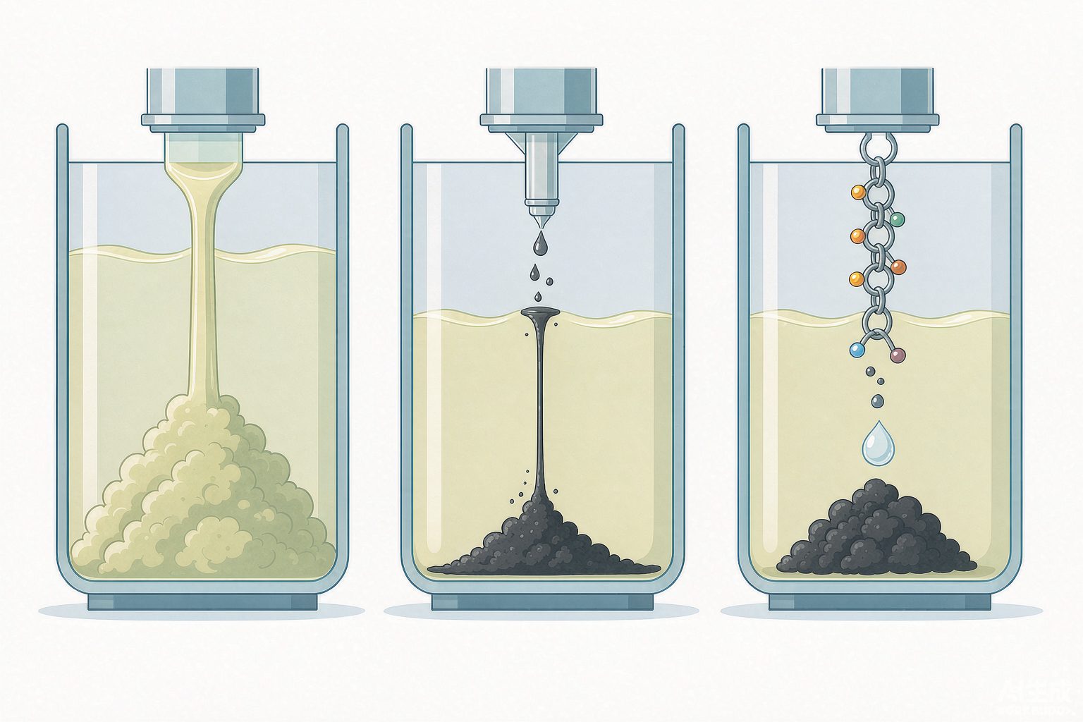
Putting hydroxide precipitation, sulfide precipitation, chelation capture, and ion exchange in the same table makes the selection logic clear: hydroxide handles the bulk load, sulfide breaks through medium-to-low concentrations, chelation capture handles the final stage, and ion exchange handles recovery and extremely low limits. They are not mutually substitutable but rather form a tiered relationship.
| Dimension | Hydroxide Precipitation | Sulfide Precipitation | Chelating Capture (DTC type) | Ion Exchange |
|---|---|---|---|---|
| Mechanism | Metals react with OH⁻ to form hydroxides | Metals react with S²⁻ to form sulfides | Chelating groups form five/six-membered ring chelates with metals | Exchange adsorption by resin functional groups |
| Applicable concentration range | Primary removal at high concentration (preferred for >50 mg/L) | Medium-high concentration and can extend to low concentration | Mainly for low-concentration polishing | Low-concentration polishing or high-value metal recovery |
| Conventionally achievable effluent | Single stage 0.5~2 mg/L; two stages 0.1~0.5 mg/L | 0.01~0.1 mg/L level | Below 0.05 mg/L level | <0.1 mg/L |
| Resistance to complexation | Weak — fails in the presence of CN⁻/NH₃/EDTA | Medium — can break partial complexation | Strong — can penetrate EDTA-type complexation | Medium — requires prior decomplexation |
| Chemicals and operation | Lime/NaOH, lowest unit price | Sodium sulfide, residual sulfur and H₂S must be controlled | Highest chemical unit price | Resin regeneration consumes acid and alkali, high depreciation |
| Sludge volume | Largest | About −40% compared with hydroxide sludge volume | 30%~35% reduction compared with conventional methods | No chemical sludge generated |
| Main risks | Re-dissolution, complexation failure, sludge volume and hazardous waste disposal costs | H₂S toxic gas, excessive residual sulfur, fine sulfide particles | Excess dosage causes colloid re-stabilization and COD increase | Competitive adsorption under high salinity and high hardness, regeneration liquid disposal |
VIII. Five Engineering Truths
First, the workshop discharge outlet is a physical pipeline, not a process step. Class I pollutants must meet standards at the workshop or workshop treatment facility discharge outlet. Once other wastewater or rainwater mixes into that facility, the nature of the sampling point changes. Independent piping networks and independent collection tanks for nickel-containing, chromium-containing, and cadmium-containing water are the most cost-effective investment on this route.
Second, there is only one pH, but there are seven metals. Mixed wastewater allows only a compromise pH, and the engineering meaning of compromise is that "there is always one item that cannot achieve the lowest solubility." To truly meet standards, the solution is not to adjust pH more precisely, but to first separate different metals in the water route.
Third, the precipitation range and the compliance window are not the same thing. Judging "normal precipitation" by visually observing flocs is the most common misjudgment on site. The basis for judgment can only be the measured effluent concentration plus the pH step test curve.
Fourth, excessive dosing is not insurance. The respective adverse effects of the three have already been written into textbooks and engineering materials: excessive reduction of Cr⁶⁺ generates [Cr₂(OH)₂SO₃]²⁻, which instead does not precipitate; when sulfide ion hardness exceeds the 1.5:1 molar ratio, residual sulfur rises above 5 mg/L and H₂S is generated as a byproduct; excessive DTC triggers colloidal restabilization and an increase in effluent COD. In this system, excess is pollution, not margin.
Fifth, what determines cost is where the sludge goes, not the unit price of chemicals. The per-ton water cost bases given in industry materials are themselves inconsistent—some materials give chemical costs of 6.8~8.2 元/m³ (sodium sulfide 4.5 + pH adjustment 1.2 + flocculation 0.8), about 25% higher than the hydroxide method; other materials give an overall operating cost of 12~18 元/m³, of which sludge disposal costs can account for about 35%. The two bases are not contradictory: the former counts only chemicals, while the latter counts sludge. Mixing them for comparison will lead to two opposite conclusions: "the sulfide method is more expensive" or "the sulfide method is cheaper." What should really be calculated is the comprehensive cost that also folds in the reduction in transportation and hazardous waste disposal fees brought by sludge reduction 40%—according to existing materials, this item alone is enough to offset the disadvantage in chemical unit price.
References
- GB 21900—2008 "Electroplating Pollutant Discharge Standard", Table 2, Table 3 and Articles 4.1.2~4.1.6.
- GB 8978—1996 "Integrated Wastewater Discharge Standard", Article 4.2.1.1 (sampling location for Category I pollutants) and the list of Category I pollutants.
- Ministry of Environmental Protection, "Reply on Issues Concerning the Pollutant Discharge Fee for Five Major Heavy Metal Pollutants", 2016-01-22.
- Former Shandong Provincial Environmental Protection Department, "Notice on Further Standardizing the Sampling Points for Category I Pollutants", 2010-06-22.
- HJ 2002—2010 "Technical Specifications for Electroplating Wastewater Treatment Engineering", requirements for classified collection and segregated treatment.
- Research on Comprehensive Electroplating Wastewater Treatment Technology and Process—Comprehensive Electroplating Wastewater from a Large Electroplating Industrial Park in Shenzhen, academic dissertation.
- Treatment of Fine Chemical Wastewater by Fenton/Air Flotation/Hydrolysis/Aeration Process, "China Water & Wastewater" 2018, 34(8): 100 m³/d engineering case.
- Li Yibin, Guo Chihao, Liang Dongdong, et al. Applied Research on Lime-Iron Salt Process for Treating High-Arsenic Waste Acid, "Nonferrous Metals (Smelting Section)" 2024.
- Lime-Iron Salt Arsenic Removal Process and Its Application in Industrial Arsenic-Containing Acidic Wastewater Treatment, review and engineering practice summary.
- Arsenic-Containing Waste Acid Treatment(Lime-Iron Salt-Ion Exchange), JOM, 2025, 77: 5632.
- Removal of Metals by Sulphide Precipitation Using Na₂S and HS⁻-Solution, ChemEngineering, 2020, 4(3): 51.
- Solubility Product Constants near 25 ℃, University of Rhode Island Department of Chemistry teaching data sheet.
- Explanation of Some Issues in the Use of Heavy Metal Capture Agents: Limitations of Neutralization-Flocculation Precipitation and Sulfide Precipitation, industry technical document.
- Metal Precipitation pH Control Guide: Quick Reference for Optimal pH Ranges for Common Metal Hydroxide Precipitation, industry technical document.
- Heavy Metal Removal from Industrial Wastewater: Three Routes of Hydroxide/Sulfide/Chelation and pH Optimization Values, technical document.
- How to Remove Heavy Metals from Wastewater—2026 Process Guide: Single-Stage and Two-Stage Precipitation Effluent Ranges, Sludge Yield, technical document.
- Efficacy Evaluation of Hardware Pickling Wastewater Treatment Based on Sulfide Precipitation: Orthogonal Experiment and Operating Cost Analysis, technical literature.
- Complete Guide to PCB Chromium-Containing Wastewater Treatment Methods: Sodium Bisulfite Reduction Precipitation Parameters, Dosage Ratios and Cost Ranges, industry technical document.
- Nickel-Containing and Copper-Containing Wastewater Treatment Case: 150 m³/d Copper-Containing Wastewater Complex Breaking and Two-Stage Precipitation Engineering, industry case document.
- Complexed Nickel Wastewater Treatment Case: 200 m³/d Electroplating Park Complexed Nickel Complex Breaking—Precipitation—Capture Process, industry case document.
- Application Data of DTC-Type Heavy Metal Removal Agents for Electroplating Wastewater, publicly available case documents from chemical suppliers.
- Compliance Points for Workshop Pretreatment of Category I Pollutants in High-Concentration Hardware Electroplating Wastewater Treatment, industry technical article.