



 Nationwide multi-industry (coal-fired power generation and combined heat and pow
 Engineering-scale (single plant 2×300 MW to 2×1000 MW; desulfurization wastewate
Whole-Plant Water Management in Thermal Power Plants: Water Leaves via the Cooling Tower, Salts Can Only Leave via the Desulfurization Tower
For units of the same capacity, the water intake quota for circulating cooling and air cooling differs by nearly seven times; yet what truly determines whether the plant-wide water system can be closed-loop is not the water volume, but a salt account—its outlet is only one.
Thermal power plants are called major water users, but strictly speaking they are water transfer stations: the vast majority of water is borrowed for one heat exchange and then returned, and the portion actually consumed is very small. The trouble is that the consumed portion ultimately leaves the plant's salt in one place, and the channel through which the plant can discharge these salts out of the system is usually only one pipe. This article breaks down the plant-wide water management scope of thermal power plants along three lines: "water intake—water consumption—salt."
I. Water intake and water consumption are two different figures, and the quota only measures the former
The water use index of thermal power plants is measured in "megawatt-hours," with the formula being water intake per unit power generation Vui = Vi ÷ Q, where Vi is the total water intake during the statistical period (including conventional and unconventional water sources such as surface water, groundwater, and reclaimed water), and Q is the power generation during the same period, in MW·h. GB/T 18916.1—2021 "Water Intake Quota Part 1: Thermal Power Generation" has two easily overlooked provisions: first, seawater cooling volume of once-through cooling systems is not counted in water intake; second, water intake statistics cover the total volume of water "used for the first time."
When these two provisions are combined, a seemingly contradictory combination emerges: once-through cooling has extremely large water intake but extremely small water consumption. In a once-through system, river water is merely borrowed for heat exchange in the condenser and then returned to the river channel as-is, leaving little in the water volume account. The data cited by India's NITI Aayog from EPRI and NRDC can illustrate this magnitude (units have been converted and unified):
| Cooling Method | Water Intake | Water Consumption | Characteristics |
|---|---|---|---|
| Once-through Cooling (Single Pass) | 75 ~ 189 | 0.37 ~ 1.19 | Large intake, small consumption; water is basically returned as is |
| Wet Cooling (Circulating Cooling Tower) | 1.89 ~ 4.16 | 1.81 ~ 4.16 | Small intake, large consumption; most of the intake water is evaporated |
| Air Cooling (Dry) | 0 | 0 | No water intake or consumption in the cooling process |
Note: The original foreign-language sources use mixed units (m³/h/MWe and m³/MWh coexist). Here, values are converted on the basis that 1 m³/h/MWe at 5000 h of annual operation is equivalent to 0.2 m³/(MW·h), and the ranges are given only to express order-of-magnitude differences. The "water consumption" of once-through cooling is actually system blowdown and leakage.
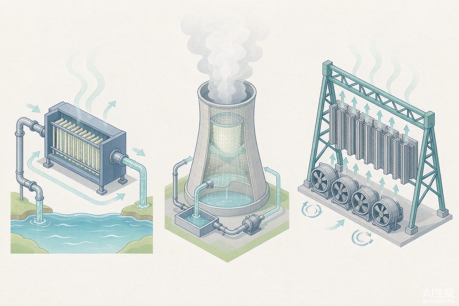
II. Three Cooling Routes, with Quotas Differing by Nearly Seven Times
The Ministry of Water Resources' "Industrial Water Quotas: Thermal Power Generation" arranges the water quotas for coal-fired generating units into a grid of 3 (leader value / advanced value / general value) × 3 (circulating cooling / once-through cooling / air cooling) × 4 (capacity tier), totaling 36 figures. It also explains the purpose of the three-tier indicators: the leader value is used to guide technological progress in water conservation and as a reference for approval of new projects in severely water-scarce areas; the advanced value is used for water resources assessment and water withdrawal permits for new, reconstruction, and expansion projects; and the general value is used for daily water management and water conservation assessment of existing enterprises.
| Capacity Tier | Leader Value | Advanced Value | General Value | General Value ÷ Leader Value |
|---|---|---|---|---|
| <300 MW | 1.73 | 1.85 | 3.20 | 1.85 |
| 300 MW Class | 1.60 | 1.70 | 2.70 | 1.69 |
| 600 MW Class | 1.54 | 1.65 | 2.35 | 1.53 |
| 1000 MW Class | 1.52 | 1.60 | 2.00 | 1.32 |
| Capacity Tier | Once-Through Cooling Leader / Advanced | Air-Cooled Leader / Advanced | Circulating Cooling Leader (Reference) | Circulating ÷ Air-Cooled (Leader Value) |
|---|---|---|---|---|
| <300 MW | 0.25 / 0.30 | 0.30 / 0.32 | 1.73 | 5.8 |
| 300 MW Class | 0.22 / 0.28 | 0.23 / 0.30 | 1.60 | 7.0 |
| 600 MW Class | 0.20 / 0.24 | 0.22 / 0.27 | 1.54 | 7.0 |
| 1000 MW Class | 0.19 / 0.22 | 0.21 / 0.24 | 1.52 | 7.2 |
[Self-calculated] The last column is obtained by dividing the values of the two original columns in this article. The larger the capacity, the wider the gap between circulating cooling and air cooling—because the evaporation of the wet cooling tower of large units rises with the circulating water volume, while the water intake of air cooling is almost limited to boiler make-up water and desulfurization make-up water.
There is also a note 2 in the quota table that deserves separate attention: when the unit uses reclaimed water, the quota shall be multiplied by an adjustment coefficient according to the cooling method — circulating cooling 1.2, air cooling 1.1, once-through cooling is not adjusted. This is a counterintuitive clause: using reclaimed water (an unconventional water source) should be encouraged, yet the quota is instead relaxed 20%. The reason lies not in policy but in physics: reclaimed water brings salt, and once the salt enters the circulating water system, it must be discharged by increasing blowdown, and more blowdown means more make-up water.
[Self-calculation] Converted according to note 2, the advanced value 1.60 of a 1000 MW-class circulating cooling unit is relaxed after using reclaimed water to 1.60 × 1.2 = 1.92 m³/(MW·h), only 4% different from the general value 2.00 without reclaimed water. In other words: the relaxation of the quota is not a reward, but an acknowledgment that this water carries salt. This layer, together with the previous section's "water intake and water consumption are two different numbers," constitutes the real way to read the quota table.
III. The water saved by air cooling is not worth the extra coal burned
Air cooling presses both the water intake and water consumption of the cooling link to near zero, with the cost written in the cold-end parameters. The energy consumption benchmarking data of the China Electricity Council gives a set of directly comparable figures: 135 600 MW supercritical wet-cooling units average a net coal consumption for power supply of 304.06 g/kWh, while 34 600 MW supercritical air-cooling units are at 321.79 g/kWh, the former being 17.73 g/kWh lower than the latter, i.e., higher by 5.83%; the gap in the 600 MW subcritical category is 317.42 versus 332.49 g/kWh, a difference of 15.07 g/kWh (4.75%). The common industry saying that "the coal consumption of air-cooling units is about 15 g/kWh higher than that of wet-cooling units of the same type" is consistent with this set of benchmarking data.
| Item | Value | Source / Formula |
|---|---|---|
| Unit capacity and annual utilization hours | 600 MW × 5000 h | Assumed values |
| Annual power generation | 3.0 × 10⁶ MW·h | 600 × 5000 |
| Difference in water intake quota (advanced value) | 1.65 − 0.27 = 1.38 m³/(MW·h) | Values from Table 3 |
| Annual water savings of air cooling | 414 万 m³ | 1.38 × 3.0 × 10⁶ |
| Monetary value of water savings | Approx. 1450 万 CNY/year | 414 万 m³ × 3.5 元/m³ |
| Extra standard coal consumption of air cooling per year | 5.32 万 t | 17.73 g/kWh × 3.0 × 10⁹ kWh |
| Monetary value of extra coal consumption | Approx. 3723 万 CNY/year | 5.32 万 t × 700 元/t |
| Net difference | Air cooling incurs approx. 2273 万 CNY/year more in expenditure | 3723 − 1450 |
Note: This table is [self-calculated], based on the assumptions of an industrial water price of 3.5 元/m³, a standard coal price of 700 元/t, annual utilization hours of 5000 h, and a coal consumption difference taken as 17.73 g/kWh for the 600 MW supercritical class. If any of the three factors—water price, coal price, or annual utilization hours—changes, the net difference will change; this table illustrates only one point: within common price ranges, the extra coal burned by air cooling costs more than the water saved, by a factor between 2 and 3. This conclusion is an estimate of this article and does not represent the position of any report.
There is also a capital account: the cold-end investment for a 2×600 MW direct air cooling system is about 5.2 亿 yuan, approximately 3.4 亿 yuan more than a wet cooling cold end of the same capacity, which translates to about 0.01 元/kWh more under 20 年 depreciation.
IV. Water Leaving the Power Plant Has Only Three Outlets
A water balance model study published in China Electric Power in 2021 年 provided the water departure distribution for supercritical units burning bituminous coal: cooling tower evaporation and wind drift losses account for 59.1%, cooling tower blowdown accounts for 19.7%, and moisture in flue gas accounts for 15.6%. These three figures together already exceed ninety percent. This means the entire plant's water conservation targets are only three—cooling system, blowdown, and flue gas—and no matter how much you squeeze the remaining links, they are just marginal. The same study also provided an elasticity coefficient: for every 1 percentage point increase in power generation efficiency, water intake per unit of power supply decreases by 3.5%, because both condenser load and flue gas volume decrease accordingly.
| Outlet | Share | Recoverable |
|---|---|---|
| Cooling tower evaporation + wind drift loss | 59.1% | Not recoverable (carried away by latent heat of vaporization, a physical necessity) |
| Cooling tower blowdown | 19.7% | Recoverable, used as desulfurization make-up water, ash and coal yard spraying |
| Moisture in flue gas | 15.6% | Recoverable, requires flue gas waste heat and moisture recovery equipment |
| Others (gypsum carry-over, boiler blowdown, etc.) | Approx. 5.6% | Partially recoverable |
The deduction of this model is well worth reading: if a wet cooling unit achieves flue gas moisture recovery of 60%, the unit water intake of a supercritical unit drops from 2.15 to 1.81 m³/(MW·h), a reduction of 19.2%; if the circulating water concentration ratio is simultaneously increased to 8, it further drops to 1.55 m³/(MW·h). And under the theoretical condition of flue gas moisture recovery of 60% for an air-cooled unit, the water intake can be reduced to zero; if semi-dry or dry desulfurization is also adopted, the power plant can theoretically become a "water supplier". This statement must be cited with the word "theoretical"—it is a model calculation result, not an operating performance record.
In terms of actual performance, Huaneng Pingliang Power Plant provides a directly comparable ledger: 4 300 MW wet-cooling units reduced power generation water consumption to 1.37 m³/(MW·h), and 2 600 MW air-cooling units reduced it to 0.23 m³/(MW·h). [Self-calculated] Compared with the quotas of the Ministry of Water Resources, 1.37 is better than the leading value 1.60 for 300 MW-class circulating cooling, and 0.23 falls between the leading value 0.22 and the advanced value 0.24 for 600 MW-class air cooling. At the same plant and on the same power generation basis, wet cooling and air cooling differ by a factor of 6—this is what the quota gap in Section 2 looks like when applied unit by unit.
The other knob is the concentration ratio. DL/T 783—2018 "Water Conservation Guidelines for Thermal Power Plants" requires the concentration ratio to be no lower than 5; public water intake permit documents show that the circulating cooling water system of the Huanjiang Li'ang Agricultural and Forestry Waste Power Generation Project has a measured concentration ratio of 6.99 and a water reuse rate of 98.43%. The higher the concentration ratio, the greater the circulating water volume that the same makeup water can carry away and the less blowdown—but the higher the salt concentration in the circulating water, which brings us exactly to the next section.
V. For the whole plant's salt, the desulfurization tower is the only outlet
The water balance of a wet desulfurization absorber tower has three outlets: water evaporated and carried away with flue gas, gypsum crystallization and entrained water, and discharged desulfurization wastewater. The first two outlets carry water away, and only the third outlet can carry dissolved salts away. This sentence determines the position of desulfurization wastewater in the entire power plant water system—it is not a byproduct of the desulfurization process, but the discharge point of the whole plant's salt balance.
The control values are written in the design code: DL/T 5196—2016 "Design Code for Limestone-Gypsum Wet Flue Gas Desulfurization Systems in Thermal Power Plants" stipulates that the operating chloride ion mass concentration in the absorber tower slurry tank shall be designed at no more than 20000 mg/L, while the corrosion resistance of materials contacting absorber tower slurry components shall be designed for no more than 40000 mg/L. The two figures govern operation and materials respectively, and are not the same quantity.
Where does chloride come from? Public estimates give two main pathways: first, the coal itself; the mass fraction of chlorine in Chinese coal is generally between 0.01% and 0.20%, averaging about 0.02%, with most below 0.05%, and the higher the ash content, the higher the chlorine in the coal; second, carryover by desulfurization process water, including dissolved chlorides in the process water and the consumption of hydrochloric acid and sodium hypochlorite in chemical water treatment. Chloride in the desulfurization slurry is continuously concentrated and can ultimately only be carried away by discharged desulfurization wastewater.
| Item | Value | Remarks |
|---|---|---|
| Make-up water for desulfurization process | 100 ~ 110 m³/h | Total for two 300 MW units |
| Of which evaporated with flue gas | approx. 90 m³/h | Accounts for more than 80% of make-up water; salts remain in the tower after evaporation |
| Conventional discharge of desulfurization wastewater | 8 ~ 20 m³/h | Varies with chlorine input and controlled slurry concentration |
| Desulfurization wastewater from 1×600 MW unit | < 15 t/h | Empirical data |
| Operating control value of chloride ions in slurry tank | ≤ 20000 mg/L | DL/T 5196—2016 |
| Anti-corrosion design value for slurry-contact components | ≤ 40000 mg/L | DL/T 5196—2016 |
Following this logic, the wastewater volume can be back-calculated. [Self-calculation] An example given in the publicly available calculation data: a 300 MW unit burns about 120 t of coal per hour; at a coal chlorine content of 0.02%, the chlorine introduced per hour is 120 × 10⁶ g × 0.02% = 24 kg. If desulfurization wastewater is discharged at 5 t/h and the slurry chlorine is controlled at 20000 mg/L, then the chlorine discharged with the wastewater per hour is 5 t × 20 kg/t = 100 kg, of which the 24 kg contributed by coal combustion corresponds to 4800 mg/L of the wastewater chlorine concentration. To put it more clearly in reverse:
| Slurry Chloride Control Concentration | Minimum Wastewater Discharge Volume | Relative Multiple | Engineering Implication |
|---|---|---|---|
| 20000 mg/L | 1.2 m³/h | 1.0 | Code design value, operating close to the upper limit |
| 10000 mg/L | 2.4 m³/h | 2.0 | Sacrificing wastewater volume for slurry quality |
| 5000 mg/L | 4.8 m³/h | 4.0 | Gypsum quality and corrosion risk significantly improved |
| 2000 mg/L | 12.0 m³/h | 10.0 | Wastewater volume increases by about one order of magnitude |
Note: This table is a simplified [self-calculated] model that only accounts for chloride introduced by coal combustion, and does not include chloride carried by desulfurization process water or chloride removed by gypsum. The actual engineering chloride balance is: desulfurization system makeup water volume × makeup water chloride concentration + inlet flue gas volume × flue gas HCl concentration = wastewater discharge volume × wastewater chloride concentration + outlet flue gas volume × outlet flue gas HCl concentration + gypsum quantity × gypsum chloride content. Common values are: slurry, i.e., wastewater, chloride concentration of about 20000 mg/L, chloride carried by outlet flue gas approximately zero, and chloride content in free-water-free gypsum of about 0.002%~0.01%.
VI. Three Knobs That Conflict with Each Other
Looking at the preceding sections together, the water system of a thermal power plant actually has only three knobs that can be turned, and their directions are not consistent.
| Knob | Turn Left | Turn Right | Where the Cost Falls |
|---|---|---|---|
| Slurry chloride control concentration | Pressed down to 2000~5000 mg/L: clean slurry, good gypsum quality, slow corrosion | Relaxed to 20000 mg/L: minimum wastewater volume | Wastewater volume (and subsequent ZLD investment) |
| Circulating water concentration ratio | Lowered to 3 cycles: low scaling and corrosion risk | Raised to 5~8 cycles: blowdown and water intake drop in tandem | Salt concentration and chemical dosage on the circulating water side |
| Desulfurization process water quality | Use only low-salinity water: small chloride input | Accept high-salinity wastewater: impressive reuse rate | Desulfurization wastewater volume (the salt does not disappear, it just enters through a different inlet) |
The common engineering practice is to assign different water quality grades to these three knobs: high-salinity chemical wastewater is sent to the desulfurization system to make limestone slurry, while low-salinity water is used for demister and pipeline flushing; circulating water blowdown is preferentially reused in wet desulfurization; and drainage from the chemical water treatment system is recovered to the circulating water system. The China Resources Power (Heze) 2×600 MW ultra-supercritical units follow exactly this sequence—all drainage from the chemical water treatment system is recovered to the circulating water system, circulating water blowdown is recovered for use in the wet desulfurization system, and 2024 年 uses 740 万 m³ of urban reclaimed water, with zero wastewater discharge.
VII. Six Sets of Figures for the Per-Ton Water Cost of Zero Liquid Discharge, Differing by More Than Ten Times
For desulfurization wastewater to achieve "Zero Liquid Discharge", it must first be reduced in volume and then solidified. There are three mainstream routes on the market—multi-effect evaporation crystallization, main flue (or bypass flue gas) evaporation, and membrane concentration coupled with evaporation—and the publicly available per-ton water costs differ greatly, and even the same route is inconsistent across different sources.
| Technical Route | Investment (10,000 CNY/(t·h)) | Operating Cost (CNY/t) | Main Constraints |
|---|---|---|---|
| Evaporation Crystallization (Multi-effect) | 250 ~ 350 | 50 ~ 80 | Requires stable and cheap steam, large footprint, softening generates large amounts of solid waste |
| Bypass Hot Flue Gas Evaporation | 100 ~ 250 | 20 ~ 30 | Spray gun clogging, ash deposition and scaling in flue duct, increased chloride in fly ash |
| Main Flue Gas Duct Evaporation | 50 ~ 100 | 10 ~ 20 | Affects boiler efficiency and unit safety, rarely applied |
| No. | Source Basis | Per-ton Water Cost |
|---|---|---|
| 1 | Electric Power Technology and Environmental Protection (multi-effect evaporation crystallization) | 50 ~ 80 元/t |
| 2 | Clean Coal Technology 2022 (turbine extraction steam triple-effect, MEE-S) | 52.0 元/t |
| 3 | Ibid. (low-temperature flue gas driven triple-effect, MEE-G) | 22.5 元/t |
| 4 | Ibid. (single-stage MVR, MVR-S) | 32.5 元/t |
| 5 | Statistics of commissioned pilot cases (Heyuan Shenzhen, Sanshui Guangdong, Changxing Zhejiang, MalianTai Ningxia, Hanchuan Hubei, etc.) | Minimum approx. 80, maximum approx. 185, average over 100 CNY/m³ |
| 6 | Multi-effect evaporation case at a certain plant | 260 元/t (steam consumption 0.35 t/t water, electricity consumption 10~15 kWh/t, total investment approx. 1.2 亿 CNY) |
[Self-calculation] Put the gap into monetary terms: for a 10 t/h desulfurization wastewater zero liquid discharge unit, based on 5000 h annual operation, the annual treatment volume is 5 万 t. If the cost per ton of water is calculated at 50 元, the annual operating cost is 250 万 yuan; if calculated at 260 元, the annual operating cost is 1300 万 yuan. For the same water stream and the same scale, the two figures differ by 1050 万 yuan/year — this is why the comparison and selection of zero liquid discharge schemes must first unify the basis before discussing equipment selection.
VIII. Salt does not disappear; it merely changes host
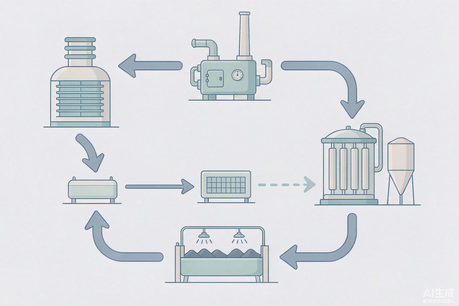
Whichever route is taken, zero liquid discharge does not make salt disappear; it merely moves the salt from "the water" into "the solid waste." Where it is moved to determines what problems the scheme will encounter in the second stage.
| Salt destination | Where the salt ultimately ends up | Subsequent constraints |
|---|---|---|
| Bypass flue gas evaporation | Enters the electrostatic precipitator with the fly ash and is captured together with the pulverized coal ash | The chloride content of fly ash increases, affecting its quality as a cement admixture |
| Evaporative crystallization | Produced as crystallized salt (can be further separated by salt type) | Whether it can be sold depends on the purity of salt separation and the local market |
| Ash and slag moisture conditioning, ash yard spraying | Enters the ash and slag, and is utilized or sealed together with the ash and slag | The destination of ash and slag (brick making, cement, landfill) imposes requirements on salt |
| Coal yard spraying | The salt returns to the coal and enters the furnace with the coal | The salt re-enters the flue gas and the desulfurization tower, forming an in-plant cycle |
The constraints of bypass flue gas evaporation are quantifiable: GB 175—2007 stipulates that the chloride ion content in cement shall not exceed 0.06%. In engineering practice, under conventional fly ash chloride content conditions, controlling the blending ratio of high-chloride pulverized coal ash within 20% usually enables the chloride ion content of the finished cement to meet this limit, but the specific value must be calculated item by item based on the measured chloride content of the pulverized coal ash, the cement mix ratio, and the auxiliary material parameters. The plant-wide zero liquid discharge project of Zhuozhou Jingyuan Thermal Power adopts a combined process of "two-stage clarification + Ultrafiltration + weak acid cation bed + Nanofiltration + Reverse Osmosis + crystallization" to treat desulfurization wastewater; the effluent is reused in the chemical water production system, and the industrial salt produced by crystallization is of high quality—this route turns salt into a product, on the premise that salt separation is thorough.
The fourth route deserves separate explanation. The 200 t/h wastewater treatment system at the Xinjiang Tianye Thermal Power Plant (2011 年 with an investment of over 1400 million yuan) enables 70%~80% of the plant's industrial wastewater to be recycled, while the remaining 20%~30% of concentrated water, which cannot be recycled due to high salinity, was connected through technical modification to 6 spray devices at the coal yard for coal yard cooling and dust suppression, saving 20~30 t of industrial deep-well water per hour, whereby the plant's wastewater basically achieves zero discharge.
IX. The Real Ledger
| Case | Scale and Investment | Key Data |
|---|---|---|
| Huaneng Pingliang Power Plant | 250.5 万 kW; investment 1.2 亿 yuan | Average annual water consumption reduced by 95 万 m³, additional wastewater and sewage utilization 125 万 m³, wastewater reuse rate increased by 42 percentage points, reclaimed water utilization rate 23.3%; 4×300 MW wet cooling 1.37 m³/(MW·h), 2×600 MW air cooling 0.23 m³/(MW·h) |
| China Resources Power (Heze) | 2×600 MW ultra-supercritical | 2024 年 municipal reclaimed water 740 万 m³, reuse volume 5.48 亿 m³, zero wastewater discharge; chemical water treatment discharge recovered to circulating water, circulating water blowdown reused for wet flue gas desulfurization |
| Zhuozhou Jingyuan Thermal Power | 2×350 MW indirect air-cooled heating | Zero liquid discharge and smart water network project investment 265 万 yuan (excluding infrastructure), comprehensive water consumption reduced from 0.42 to below 0.20 m³/(MW·h), annual water savings 70 万 m³ |
| Shenhua Guoneng Yuanyanghu Power Plant | Phase I 2×660 MW direct air cooling; Phase II 2×1000 MW indirect air cooling | Indirect air cooling saves 6.74 万 t of standard coal per year compared with similar direct air-cooled units; all wastewater used for dry ash and slag wetting, coal yard spraying, desulfurization process and plant greening, saving nearly 200 万 yuan in water resource costs annually |
| China Coal Hami Power Generation | 2×660 MW air cooling, municipal reclaimed water source | 2022 年 water intake per unit power generation 0.17 m³/MWh; dry ash and slag removal reduces 30 万 m³ annually; Ultrafiltration (UF) backwash discharge reused 10 万 m³ annually; chemical Reverse Osmosis (RO) concentrate discharged to desulfurization process water tank reduces desulfurization water use by 15 万 m³; coal handling system wastewater utilized 8 万 m³ annually |
| Huaneng Yangluo Power Plant | 2570 MW; proposed investment of approximately 1 亿 yuan for comprehensive treatment | All ash and slag from 6 units collected and discharged dry, saving more than 1000 万 m³ of raw water; average power generation water intake during water balance test 924 m³/h, water reuse rate greater than 91% |
| Datang Qinling Power Generation | Investment 2096.6 万 yuan, three EPC lots | Retrofitted water management, coal-containing wastewater, industrial wastewater, desulfurization wastewater and terminal wastewater systems, achieving zero liquid discharge (ZLD) for the entire plant, with significant reduction in water intake for coal yard spraying and ash/slag wetting |
| Xinjiang Tianye Thermal Power Plant | 200 t/h wastewater system, 2011 年 investment of over 1400 ten thousand yuan | 70%~80% industrial wastewater recycled; 20%~30% high-salinity concentrate connected to 6 spray devices at coal yard, saving 20~30 t of deep well water per hour |
| Huanjiang Li'ang (Biomass Power Generation) | Per water intake permit approval basis | Water intake per unit product 3.73 m³/(MW·h), water reuse rate 98.43%, circulating water concentration ratio 6.99 times |
| Huaibei Shenergy Power Generation | 2025 年 power generation 551.3 万 MW·h | Total water use 782.3 万 m³ (including approximately 160 万 m³ reclaimed water), water intake per unit power generation 1.37 m³/(MW·h), three-year average 1.29 m³/(MW·h) |
X. Engineering Truths
Truth 1: The first savings from plant-wide water conservation usually come not from water treatment but from the ash and slag system. At Yangluo Power Plant, all ash and slag from 6 units is collected and discharged dry; this single measure saves more than 1000 万 m³ of raw water; dry ash and slag removal at China Coal Hami reduces water use by about 30 万 m³ per year. The ash-flushing water volume of early wet ash removal systems could reach 200~400 m³/h or even more, on the same order of magnitude as the plant's total water intake.
Truth 2: Three-level metering and water balance testing are preconditions, not wrap-up work. GB/T 26925—2025 "Water-saving enterprises — Thermal power industry" lists water balance testing among the management indicators, requiring implementation in accordance with GB/T 12452 and DL/T 606.5 and retention of a complete report; the equipping rate of three-level metering instruments should reach 100%; annual investment in water-saving technological transformation shall be no less than 5% of water fee expenditure. The standard also tightens the water intake per unit power generation for 600 MW-level circulating cooling units from 1.65 to 1.54 m³/(MW·h), a reduction of 6.7%, and requires the reuse rate of circulating cooling water blowdown to be greater than 90%, the condensate recovery rate to be greater than 95%, the wastewater reuse rate to be greater than 90%, and the compliant discharge rate of wastewater to be 100%.
Truth 3: Reusing circulating water blowdown in the desulfurization system is the most fixed pathway in this water system. Heze, Yangluo, and Hami all followed the same route: circulating water blowdown (or chemical Reverse Osmosis / RO concentrate) is first sent to the desulfurization process water tank. The reason is that the desulfurization system has relatively loose water quality requirements, and it happens to be the terminal outlet for salt in the entire plant.
Truth 4: The final users of terminal wastewater are the ash yard, coal yard, and slag yard, not the wastewater treatment station. How much water these three locations can absorb is constrained by the chloride and salt requirements of comprehensive ash and slag utilization — the upper limits of chloride ion 0.06% in cement admixtures and 20% fly ash blending ratio in turn limit how much salt the zero-discharge terminal can put into the ash.
Truth 5: What really constrains zero liquid discharge projects is site, steam, and solid waste outlets, not the water treatment technology itself. Multi-effect evaporation crystallization requires an equipment investment of 250~350 万 yuan/(t·h) per ton of water, large sites, and stable cheap steam. Public pilot cases have explicitly mentioned constraints such as "the softening process consumes large amounts of chemicals and generates large amounts of solid waste," "membrane concentration equipment fouling and clogging," and "scaling and corrosion of thermal concentration and evaporation crystallization equipment."
References
- State Administration for Market Regulation, Standardization Administration of China. Norm of water intake—Part 1: Thermal power generation: GB/T 18916.1—2021.
- Ministry of Water Resources. Industrial water intake quota: Thermal power generation (including the three-tier quota table, reclaimed water adjustment coefficients, and correction notes for heating units).
- State Administration for Market Regulation, Standardization Administration of China. Water-saving enterprises—Thermal power industry: GB/T 26925—2025 (including the technical indicator table and the scoring method for management indicators).
- National Energy Administration. Guidelines for water conservation in thermal power plants: DL/T 783—2018 (the concentration ratio should not be lower than 5).
- National Energy Administration. Design code for limestone-gypsum wet flue gas desulfurization systems in thermal power plants: DL/T 5196—2016 (slurry tank chloride ion 20000 mg/L, component anti-corrosion 40000 mg/L).
- State Administration for Market Regulation. Common Portland cement: GB 175—2007 (chloride ion not exceeding 0.06%).
- Ministry of Water Resources. General principles of water balance testing: GB/T 12452.
- Electric power industry standard. Guidelines for energy balance in thermal power plants—Part 5: Water balance test: DL/T 606.5.
- Water balance model and water-saving analysis of coal-fired power plants. China Electric Power, 2021 (water loss distribution 59.1%/19.7%/15.6%, power generation efficiency elasticity 3.5%, flue gas moisture recovery and concentration ratio scenarios).
- In-depth analysis of wastewater discharge from limestone-gypsum wet desulfurization. China Electric Power, 2019 (determination of desulfurization wastewater volume by total Cl⁻ balance, classified application of process water, desulfurization system as the terminal user of plant-wide industrial wastewater).
- Determination of desulfurization wastewater volume in coal-fired power plants under wastewater "zero discharge" (including chlorine mass fraction in coal 0.01%~0.20%, average 0.02%, 300 MW unit 24 kg/h chlorine and 4800 mg/L contribution, chlorine balance equation). Reposted by Gansu Provincial Environmental Protection Industry Association.
- Research on the generation and treatment process of limestone-gypsum wet desulfurization wastewater (desulfurization wastewater chlorine balance formula and 2×300 MW 8~12 t/h, 1×600 MW less than 15 t/h empirical value). BJX Environmental Protection Network.
- Comparison of zero liquid discharge treatment technologies for desulfurization wastewater in coal-fired power plants (investment and operating costs of evaporation crystallization, main flue evaporation, and bypass hot flue gas evaporation). Electric Power Technology and Environmental Protection.
- Design and analysis of thermal zero liquid discharge system for desulfurization wastewater in coal-fired power plants. Clean Coal Technology, 2022 (MEE-S 52.0 元/t, MEE-G 22.5 元/t, MVR-S 32.5 元/t, MEE-MVR 30.2 元/t, steam 65 元/t, electricity 0.416 元/kWh).
- Research progress and standard revision recommendations for desulfurization wastewater treatment technology in coal-fired power plants in China. Clean Coal Technology, 2017 (multi-effect evaporation at a certain plant 0.35 t steam/t water, 10~15 kWh/t, operating costs and total investment; Jiaozuo Wanfang bypass flue evaporation case).
- Full membrane advanced purification system for desulfurization wastewater (domestic commissioned evaporation crystallization pilot investment and O&M cost ranges per ton of water, effluent destination of the three-tank process). Wastewater Treatment Engineering Network.
- Revision compilation notes for GB/T 26925 "Water-saving enterprises—Thermal power industry" (boiler make-up water rate 3% and within 100 万 kW class 1%, 2×300 MW desulfurization make-up water 100~110 m³/h, desulfurization wastewater 8~20 m³/h, wet ash removal flushing water volume 200~400 m³/h).
- Technical entries on air-cooled turbine units and air-cooled islands (air-cooled units with high coal consumption 10~15 g/kWh and 3%~8%, annual water savings of air-cooled units at Lingwu Power Plant, indirect air cooling and digital twin retrofit).
- Water conservation in thermal power units—air cooling is the inevitable choice: an interview with China Electric Power Planning & Engineering Institute (air cooling saves more than 80% water compared with wet cooling, coal consumption is about 15 g/kWh higher, and the water consumption index can be reduced to below 0.06 m³/(s·GW)). China Energy News.
- Design and operation of large direct air-cooled power stations (water consumption of dry ash removal desulfurization units 0.15 m³/(s·GW), water savings compared with wet-cooled units of the same capacity 4/5~3/4, investment comparison of 2×600 MW direct air-cooled cold ends).
- China Electricity Council energy consumption benchmarking data (600 MW supercritical wet cooling 304.06 and air cooling 321.79 g/kWh; 600 MW subcritical 317.42 and 332.49 g/kWh).
- Shandong Provincial Department of Water Resources. Mudan District: Water-saving management and water-saving technology innovation in thermal power plants (China Resources Power Heze 2×600 MW reclaimed water 740 万 m³, reuse volume 5.48 亿 m³, wastewater discharge zero). 2025-12.
- Wuhan Municipal Water Authority. Water-saving experience of Huaneng Yangluo Power Plant (dry collection and dry discharge saves more than 1000 万 m³ of raw water, average power generation water intake 924 m³/h, water reuse rate greater than 91%). 2021-05.
- Yellow River Water Resources Commission of the Ministry of Water Resources. Water conservation at Huaneng Pingliang Power Generation Co., Ltd. (investment 1.2 亿 yuan, average annual water consumption reduction 95 万 m³, additional wastewater reuse 125 万 m³, wastewater reuse rate increased by 42 percentage points, wet cooling 1.37 and air cooling 0.23 m³/(MW·h)). 2024-08.
- Ministry of Industry and Information Technology. Typical cases in the coal and power industries: plant-wide zero water discharge and smart water network construction project (Zhuozhou Jingyuan Thermal Power 2×350 MW indirect air cooling, investment 265 万 yuan, comprehensive water consumption 0.42 reduced to below 0.20 m³/(MW·h), annual water savings 70 万 m³) and bypass flue gas evaporation zero liquid discharge technology for thermal power desulfurization wastewater.
- Xinhua News Agency Ningxia Channel. Shenhua Guoneng Ningxia Coal Power Company builds an ecological power plant (Phase II indirect air cooling of Yuanyanghu Power Plant saves 6.74 万 t of standard coal annually, and zero wastewater discharge saves nearly 200 万 yuan in water resource costs annually).
- Yellow River Water Resources Commission of the Ministry of Water Resources. China Coal Hami Power Generation Co., Ltd. upgrades water use processes to promote whole-process water conservation (2022 年 water intake per unit power generation 0.17 m³/MWh, dry ash and slag removal reduces 30 万 m³ annually, desulfurization reduces water use by 15 万 m³). 2024-08.
- Public reports on wastewater and water-saving retrofit of Datang Qinling Power Generation Co., Ltd. (investment 2096.6 万 yuan in three EPC lots, plant-wide zero wastewater discharge).
- Tianye Thermal Power Plant uses high-salinity wastewater for coal yard spraying (200 t/h wastewater system 2011 年 investment of more than 1400 ten thousand yuan, 70%~80% recycled, 20%~30% concentrated water connected to 6 spray devices in the coal yard). China Water Network.
- Guangxi Zhuang Autonomous Region Department of Water Resources. Water intake administrative license decision for Huanjiang Li'ang agricultural and forestry waste power generation project: Gui Shui Xu Ke Jue [2025] No. 153 (water intake per unit product 3.73 m³/(MW·h), reuse rate 98.43%, concentration ratio 6.99).
- Jiangxi Provincial Department of Water Resources. Water intake permit approval for Datang Fuzhou Power Plant expansion project: Gan Shui Xu Ke Zi [2023] No. 72 (water intake per unit power generation 1.519 m³/(MW·h)) and approval for Sateri (Jiujiang) cogeneration project: Gan Shui Zi Yuan Zi [2022] No. 21 (1.47 m³/(MW·h)).
- Huaibei Municipal Water Authority. One of the first batch of national water-saving management system certification pilot water users (Huaibei Shenneng Power Generation 2025 年 power generation 551.3 万 MW·h, total water use 782.3 万 m³, water intake per unit power generation 1.37 m³/(MW·h)).
- Jilin Provincial Department of Water Resources et al. National reference list of advanced values for water intake quotas (2024 年) and water intake quotas for major industrial products of industrial enterprises in Jiangxi Province: DB36/T 420—2019 (two public citations referring to different "advanced values").
- India NITI Aayog. Energy-Water Nexus and Efficient Water-Cooling Thermal Power Plants (citing water intake and consumption data for three cooling methods from EPRI 2002, NRDC 2014, and Zhai & Rubin 2010).
The data in this article are all taken from public standards, government public documents, journal papers, and publicly available corporate reports, with sources cited item by item. The parts marked [self-calculated] in the text (the quota ratios of the three cooling routes, the two accounts of air cooling and wet cooling, the relationship between desulfurization wastewater volume and control concentration, and the comparison of annual operating costs for zero liquid discharge) all provide formulas and explicit assumptions and can be verified; among them, Table 4 is an estimation in this article, not a ready-made conclusion from any report. Items involving commercial technical materials have been marked in the main text as to their nature and treated as directional references. Water quality in thermal power plants varies by plant, by coal, and by unit, and any scheme must be checked against actual water quality and water balance test data.
您提供的内容似乎不完整,缺少需要翻译的中文文本。请提供待翻译的中文内容,我将根据术语表为您翻译成地道的英文。