



 Across multiple industries nationwide (feedwater and desulfurization in coal-fir
 Pilot to engineering scale (DN15 to DN1000; single-valve flow rate 0.1 to 2000 m
Industrial Water Treatment Control Valves: Size Is Not Pipe Diameter, and Rangeability Is Not 30
Pumps fail at the suction inlet, valves fail on the discharge side; pumps fear "can't draw it up," valves fear "can't throttle it down." Judging these two things with the same set of experience points in opposite directions.
A DN100 control valve installed on a DN100 pipe looks perfectly right. Yet on site it operates year-round within twenty percent opening; the operator thinks he is "adjusting finely," the maintenance worker thinks the medium is dirty, and the procurement staff thinks this brand's valves are poor quality. The real reason is often so simple that no one wants to believe it: this valve has been oversized since the day it was selected. And the saying "valve size can be two sizes smaller than the pipe" is written on page two of many selection manuals, yet almost no one follows it.
I. Why a DN100 valve operates year-round at 13%
Let's calculate first. A demineralized water transfer branch pipe DN100, design flow 42 m³/h (corresponding to a pipe velocity of 1.50 m/s, which is a very normal value). Actual operation runs only 12 m³/h year-round, with available differential pressure across the valve 1 bar. According to the definition of Kv:
While the rated Kv of a DN100 single-seat control valve is about 100, or even 160. Taking 100 for calculation, under linear characteristics the required opening is only 12%. This is the entire origin of "a DN100 valve opening at 12%" — the valve is not broken; its flow capacity is eight times the process requirement.
Conversely, if a DN50 valve is installed (rated Kv approx. 40), the opening under the same conditions is about 30%; with DN40 (Kv approx. 25), the opening is about 48%, which exactly falls within the commonly recommended engineering range. Not an inch of pipe was changed, the valve is two sizes smaller, and money is saved.
Why can these two things be inconsistent? Because pipe diameter and valve size are governed by two different constraints. Pipe diameter is determined by "transport velocity" and "pipe network economics"; DN100 running at 42 m³/h under 1.5 m/s is perfectly reasonable, and this choice is not wrong. Valve size is determined by "how much flow must pass at a given differential pressure"; it only cares about Kv. No design code requires that the control valve size equal the pipe size. On the contrary, the common practice is: the control valve size can be two sizes smaller than the connecting pipe — when the connecting pipe is DN250, the control valve can be selected as DN150 [5].
This rule has a precondition in engineering, which will be calculated in Section VII: the reduction must be expanded together with the outlet, otherwise the money saved on the valve will turn into wear on the downstream pipe.
II. First Align the Three Units: Cv, Kv, DN
The first step of a selection error rarely occurs in the calculation, but at the moment the numbers from the catalog are entered into the software. There are only two flow capacity units in the world, and they are mixed in valve catalogs, selection software, and technical agreements, and none of the conversion factors is an integer.
| Symbol | Definition (medium and conditions) | Unit | Conversion |
|---|---|---|---|
| Cv | 60 °F (15.6 ℃) clean water, with a pressure drop of 1 psi across the valve, the number of US gallons per minute passing through | US gal/min | Cv ≈ 1.167 Kv |
| Kv | 5~40 ℃ clean water, with a pressure drop of 1 bar across the valve, the number of cubic meters per hour passing through | m³/h | Kv ≈ 0.857 Cv |
| DN | Nominal diameter, describing only the connection size, not the flow capacity | mm | No fixed correspondence with Kv |
These two definitions appear to differ only between imperial and metric units, but in reality they differ by about 17%. If a valve marked Kv = 40 is entered into imported sizing software as Cv = 40, the software will consider it to have a flow capacity of only 34, and the result selected will be "insufficient flow rate"; in the field, this leads to only one conclusion: the pump was undersized. Conversely, if Cv is entered as Kv, the valve will be 17% oversized, directly pushing it toward a small opening position. Errors in either direction will not be exposed during commissioning; they will only come back six months later in the form of "erosion," "internal leakage," or "unstable control."
The trickier part is the relationship between DN and Kv. GB/T 4213—2008 only specifies that "the deviation between the measured value and the specified value of the rated flow coefficient shall not exceed ±10% (±20% when Kv ≤ 5)" [3]; it guarantees manufacturing consistency for the same model, not a one-to-one correspondence between nominal size and flow capacity. For the same DN100 valve body, swapping in an equal-percentage trim, a linear trim, or a cage-type multi-stage trim can change Kv by a factor of two or three. So the question "what is the Kv of a DN100 valve" has no answer in a catalog—only on a specific model.
III. The Three Pressure-Differential Thresholds: Cavitation Inception, Choked Flow, and Flashing
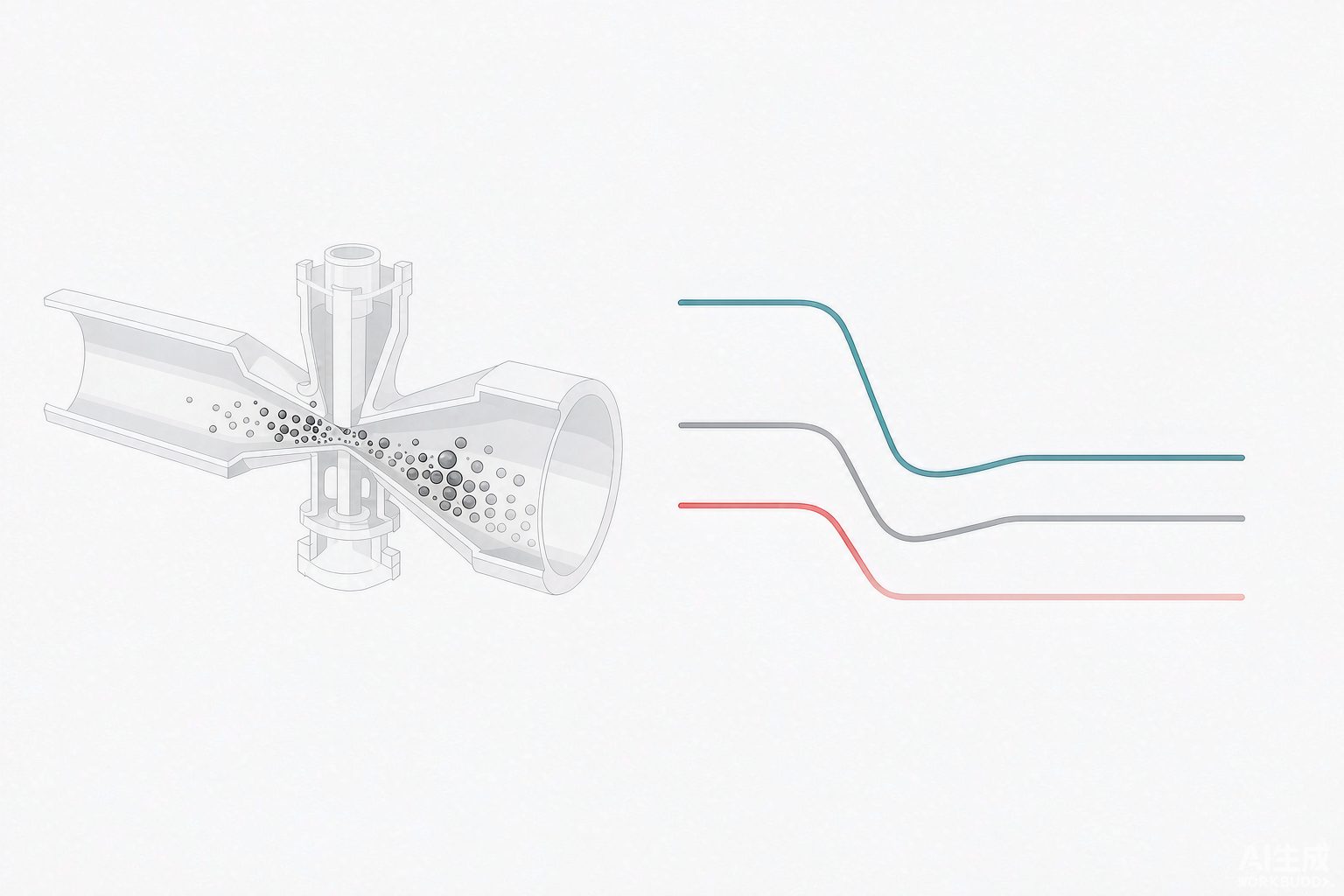
Control valves in water treatment are, most of the time, not "regulating"—they are "consuming head." When 0.6 MPa feed water enters an atmospheric tank, the entire 5 bar pressure differential must be dissipated across this valve. And when liquid passes through the reduced section inside the valve, the pressure does not drop smoothly—it first falls to a trough lower than the downstream pressure (at the vena contracta), then partially recovers in the valve cavity and downstream diffuser section. This "drop-then-recover" profile determines three things.
ΔPchoked = FL² × (P₁ − FF × Pv)
FF = 0.96 − 0.28 × √(Pv / Pc)
P₁ absolute pressure upstream of the valve; Pv saturated vapor pressure at operating temperature; Pc thermodynamic critical pressure (22.064 MPa for water); FL liquid pressure recovery factor; xFz allowable pressure differential ratio
The three thresholds correspond to three states, and the criterion is a single dividing line: which is higher, the downstream pressure P₂ or the saturated vapor pressure Pv.
- P₂ > Pv, and ΔP exceeds the cavitation inception value: Bubbles form at the vena contracta and collapse in the pressure recovery zone downstream of the valve. The collapse point is right at the valve body inner wall, the plug, and the seat, where microjets repeatedly hammer the metal, forming honeycomb-shaped pits and producing a sound like gravel flowing past. This is cavitation.
- P₂ < Pv: The bubbles do not collapse even after leaving the valve, and the entire downstream piping carries a vapor-liquid two-phase flow. This is flashing. The damage form is completely different—not pitting, but smooth grooves running along the flow direction, located in the valve body and downstream pipe, not at the seat.
- ΔP exceeds the choked-flow pressure differential: The vapor cavity at the vena contracta has already occupied the entire flow cross-section; further reducing downstream pressure or opening the valve wider will not increase flow. This is choked flow.
Let's plug in the most common water treatment condition and calculate: upstream of the valve 0.6 MPa (absolute pressure, roughly equivalent to 0.5 MPa gauge feed water), water temperature 25 ℃, Pv = 3.17 kPa, FF = 0.957.
| Valve Type | FL | xFz | Cavitation Onset ΔP | Choked Flow ΔP |
|---|---|---|---|---|
| Centerline Butterfly Valve | 0.65 | 0.35 | 2.1 | 2.5 |
| V-port Control Ball Valve | 0.60 | 0.30 | 1.8 | 2.2 |
| Single-Seat / Cage Valve | 0.85 | 0.55 | 3.3 | 4.3 |
| Multi-Stage Pressure-Reduction Valve | 0.96 | 0.85 | 5.1 | 5.5 |
One thing to note when reading this table: the inlet is 0.6 MPa and the outlet is an atmospheric tank, so the pressure differential is 5 bar. That is to say, a DN100 centerline butterfly valve at this location has already exceeded the choked flow threshold (2.5 bar) from its very first day of operation, and has been cavitating at least since 2.1 bar. The on-site remark that "this butterfly valve gives about the same flow at 40% as at 80%" is not an actuator problem—it is physics.
Here is a very easily overlooked directional issue. The Cv formula uses ΔP, and once choked flow occurs, ΔP must be replaced with ΔPchoked; otherwise the calculated Cv is too large and the selected valve is too small. In the entire sizing process, this is the only place where "a calculation error causes undersizing"—in all other steps (margin, rounding, size enlargement), calculation errors all tend toward oversizing. Therefore, this item cannot be omitted.
IV. FL squared is exactly the portion of P₁ you can use
The numbers in the last three columns of Table 2 are not a coincidence. Dividing ΔPchoked by P₁ gives a constant that hardly changes with pressure or temperature:
| FL | FL² | Meaning: how much of P₁ can be dissipated at most | Typical valve type |
|---|---|---|---|
| 0.60 | 36% | Only 36% of the inlet pressure can be dissipated | V-port ball valve |
| 0.65 | 42% | 42% | Centerline / double-offset butterfly valve |
| 0.85 | 72% | 72% | Single-seat valve, cage valve |
| 0.96 | 92% | 92% | Multi-stage pressure reduction, labyrinth type |
This algorithm has been verified under three inlet pressures: the ratio of the butterfly valve's choked pressure differential to P₁ is constantly 42% (1.69 at 4 bar, 2.53 at 6 bar, 6.76 at 16 bar). Therefore, the question "how much pressure differential can this valve withstand" is itself the wrong question; the correct question is "what percentage of the inlet pressure can this valve withstand." When the inlet pressure is increased, the pressure differential value that can be dissipated increases proportionally, while the ratio remains unchanged.
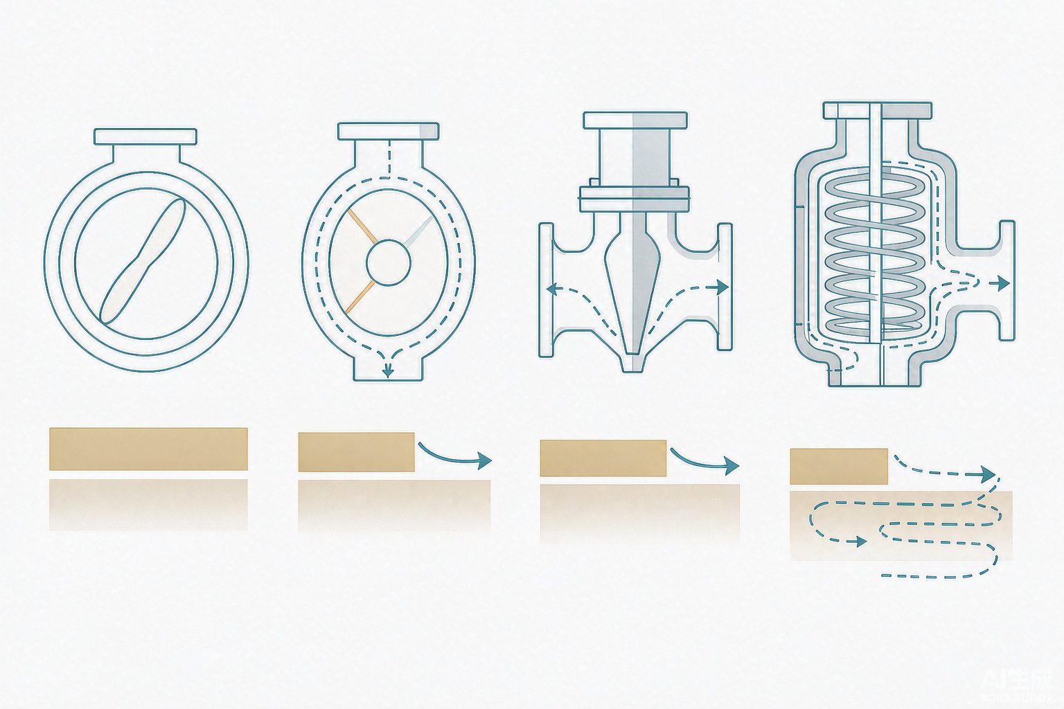
Then comes the most counterintuitive point in this article: the smoother the flow path and the smaller the pressure loss of a valve, the smaller its FL, and the smaller the pressure differential it can handle.
The reason lies in the words "pressure recovery." The flow paths of butterfly valves and ball valves are almost straight, and beyond the reduced-diameter section they quickly expand, so the downstream diffuser section recovers a great deal of pressure—the more aggressively it recovers, the lower the pressure must have been at the reduced-diameter section. The lower the pressure at the reduced-diameter section, the more easily it falls below Pv, and the more easily bubbles form. Conversely, the flow path of a single-seat valve is tortuous, and that of a multi-stage valve is cut into more than a dozen segments, each bearing only a small portion of the pressure drop, so the pressure never has a chance to fall to the trough, and bubbles cannot grow.
The same "low resistance" is an advantage in the energy-consumption ledger but a disadvantage in the cavitation ledger. This is why, at locations such as desulfurization slurry, demineralized water, and high-pressure-differential discharge, engineering practice would rather use a clumsy multi-stage pressure-reducing valve with high pressure loss than the "more efficient" butterfly valve. The little pressure head saved by using a butterfly valve will be paid back six months later in the form of replacing valve internals.
V. Temperature pushes the threshold down: Pv is a function of operating temperature
Table 2 uses water at 25 ℃. In water treatment systems, the truly troublesome thing is never 25 ℃.
| Water Temperature ℃ | Pv (kPa, Absolute Pressure) | FF | Engineering Implication |
|---|---|---|---|
| 20 | 2.34 | 0.957 | Ambient-temperature clean water; the cavitation threshold is almost entirely determined by the pressure differential |
| 40 | 7.38 | 0.955 | Summer circulating water return temperature range |
| 60 | 19.9 | 0.952 | Hot water systems, some process reuse water |
| 80 | 47.4 | 0.947 | Upstream of deaerator, some condensate |
| 100 | 101.3 | 0.941 | Equal to one atmosphere: will inevitably flash at atmospheric pressure |
| 120 | 198.5 | 0.933 | High-temperature condensate, secondary steam systems |
| 175 | 892 | 0.904 | Medium-pressure boiler feedwater |
Pv approximately doubles for every 20 ℃ increase. This rule brings two very specific consequences.
The first: 100 ℃ is the watershed. At 100 ℃, Pv is exactly one standard atmosphere; any valve that brings the water to atmospheric pressure is flashing, regardless of valve type, material, or opening. Flashing is not "the valve was poorly selected"; it is "the temperature of this water dictates that it must turn to steam at atmospheric pressure."
The second: The same valve in summer and in winter is not the same valve. At a circulating water temperature of 15 ℃, Pv = 1.7 kPa; at 35 ℃, 5.6 kPa—both look small, but when the downstream pressure is already close to atmospheric, this difference directly determines the cavitation inception pressure drop. Calculating once with the design-condition 25 ℃ and then delivering is a very typical time-lag pitfall: by July, abnormal noise starts on site.
Picking up the deaerator example from the previous article: the feedwater at 104 ℃ has Pv ≈ 117 kPa, exceeding atmospheric pressure. Therefore the suction inlet of the feedwater pump must be raised above 20 m water column to avoid cavitation; applying the same number to valves, the conclusion is—any control valve downstream of the deaerator, as long as its downstream pressure is below 117 kPa, is flashing. These are not two problems; they are the same Pv being tested twice at two locations.
Six, the triple discount on rangeability: sample 30, engineering 8
The rangeability printed on valve samples is usually 30:1, with better ones stating 50:1 or even 100:1. This number is not fabricated, but it describes "the ratio of Kv across the full stroke from 0 to 100%." In engineering practice, however, this valve will not operate at 0% and 100%.
| Stage | Source of Discount | Remaining Adjustable Ratio |
|---|---|---|
| Sample nominal | Ratio of Kv over the full stroke 0~100% | 30 |
| First discount: operating only within 10%~90% opening | Ratio of Kv within this range = 300.8 | approx. 15 |
| Second discount: series pipeline S = 0.3 | × √0.3 = 0.548 | approx. 8.2 |
| Second discount: series pipeline S = 0.1 | × √0.1 = 0.316 | approx. 4.7 |
| Second discount: series pipeline S = 0.05 | × √0.05 = 0.224 | approx. 3.4 |
S is the ratio of the pressure drop across the valve when fully open to the total system pressure drop (including the valve). It couples the "valve characteristic" with the "pipeline characteristic": the closer S is to 1, the smaller the pipeline resistance, and the closer the valve's actual working characteristic is to the ideal curve given by the sample; the smaller S is, the larger the proportion of pipeline resistance, the flatter the characteristic curve is compressed, and the faster the adjustable ratio drops.
Here is an unavoidable dilemma that must be acknowledged: With a large S, controllability is good, but head is wasted across the valve, the pump must be oversized, and electricity costs are higher year-round; with a small S, energy is saved, but the characteristic is distorted and the turndown ratio drops below 5, making small-flow conditions unstable to control. Early textbooks recommended S = 0.3–0.6; in recent years, engineering practice has generally lowered this to 0.1–0.3, and high-pressure systems can go to 0.05 [6] — this change itself is the result of "energy-saving pressure" overriding "control quality." When performing turndown ratio verification in sizing calculations, it is customary to take R = 10 directly; the reason is exactly this: 30 is the ideal value, while 10 is the value that can actually be used for calculations.
The most direct use of this calculation is: calculate the maximum/minimum flow ratio of the operating condition. If this ratio is 6:1, and at S = 0.1 the available turndown ratio is only 4.7, then this valve will not be sufficient no matter how large it is selected — if selected too large, small flows cannot be controlled; if selected too small, the maximum flow cannot pass. The only way out is split ranging: two valves, large and small, in parallel; small flows go through the small valve, and above the threshold switch to the large valve. In water treatment, the three locations most likely to encounter this situation are chemical dosing, aeration branch lines, and return sludge.
Seven, small opening is not "imprecise control," it is "in a high-speed jet"
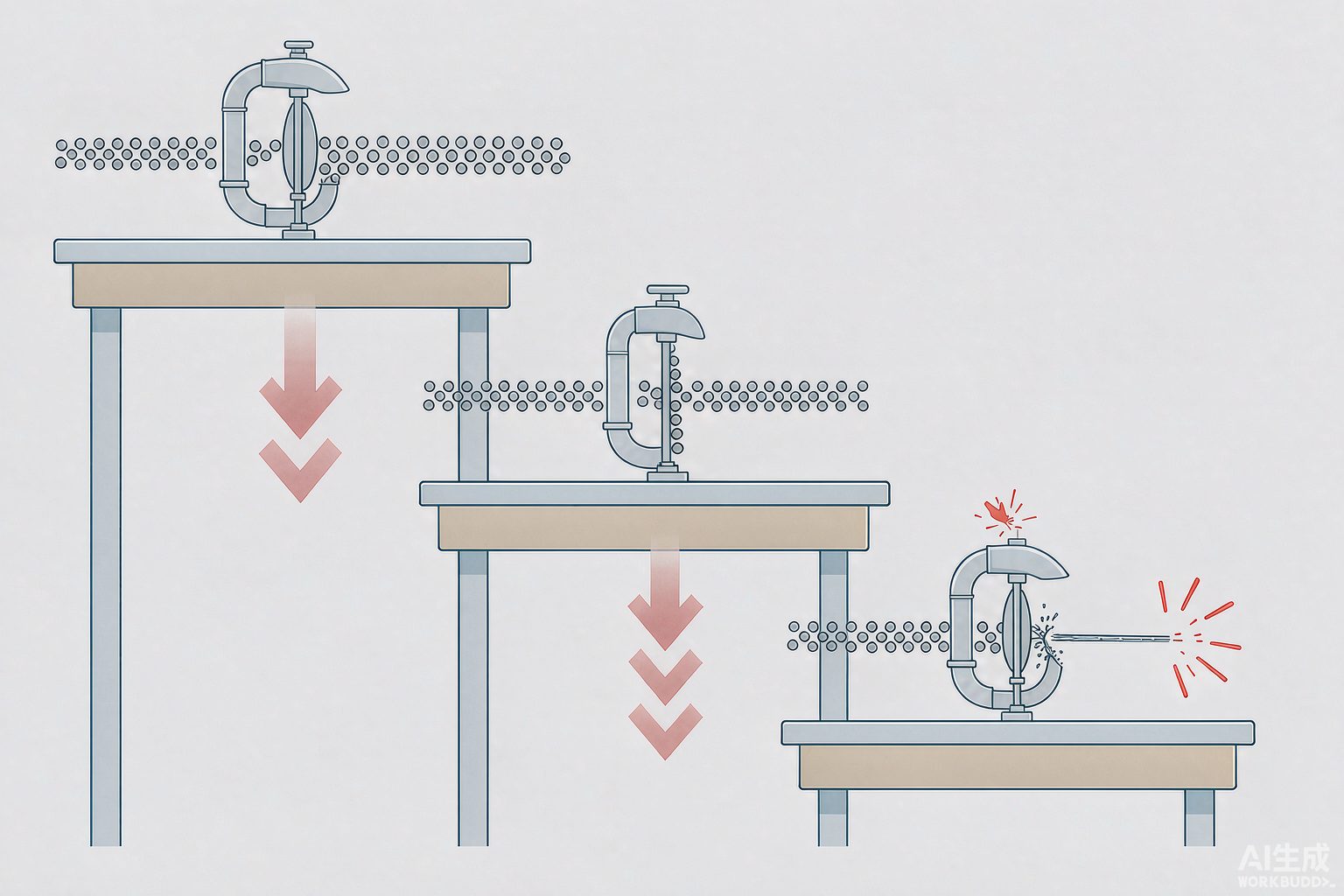
Many people understand "small valve opening" as an accuracy issue, but in reality it is first and foremost a life issue. Under equal-percentage characteristics, the flow area at 20% opening is only a few percent of that at full open; the same flow must be forced through a much smaller orifice, and the local velocity can be more than ten times that at full open. The erosion rate is proportional to the 2–4 power of velocity — double the velocity, and the wear rate increases by 4 to 16 times.
This is the origin of "wire drawing": at very small openings, the sealing surface is repeatedly scraped by a high-speed solids-laden jet and quickly wears a groove. When fully closed it may still look fairly tight, but as soon as it opens it leaks, and the more it leaks the more it erodes, and the more it erodes the larger the leak becomes. The "selected too large" issue mentioned in the previous section ultimately gets settled here.
| Valve Size | Non-Flashing Condition | Flashing Condition |
|---|---|---|
| ≤ DN50 | 10 | 5 |
| DN65 ~ DN150 | 8 | 4 |
| ≥ DN200 | 6 | 3 |
The notes to Table 6 also include one item: sleeve valves and anti-cavitation control valves are permitted to be relaxed to 1.5 times the values in the table above. Another commonly cited set of values is the downstream piping flow velocity — 3~5 m/s for clean liquids and 1.5~3 m/s for media containing solids [17]. These two sets of figures do not conflict: one covers the inside of the valve, the other the downstream piping, but both point to the same thing: the downstream piping must be verified separately.
Now let us return to the statement in Section 1 that "the valve can be two sizes smaller than the pipe" and work out its cost clearly. For the same stream of 42 m³/h water:
| Downstream pipe inner diameter | Flow velocity at 42 m³/h | Flow velocity at 12 m³/h | Assessment |
|---|---|---|---|
| DN100 (inner diameter approx. 102 mm) | 1.50 m/s | 0.53 m/s | Normal |
| DN80 (inner diameter approx. 78 mm) | 2.35 m/s | 0.83 m/s | Normal |
| DN50 (inner diameter approx. 51 mm) | 6.02 m/s | 2.13 m/s | Exceeds limit at full load |
Therefore, the complete version of the rule "valve size two steps smaller than the pipe" is: the valve body may be reduced, but the pipe after the valve must be expanded, and a straight pipe section of at least 10 times the pipe diameter must be left after the valve to let the jet dissipate. A DN100 pipe fitted with a DN50 valve, immediately expanded back to DN100 after the valve, with flow velocity dropping from 6.02 m/s to 1.50 m/s—if this step is skipped, the money saved on the valve will be paid back section by section along the downstream 10D pipe.
VIII. Valve Types and Failure Modes in Each Process Section
There is no "one valve fits all" in water treatment. Within the same plant, the media at six or seven locations—influent, aeration, sludge discharge, chemical dosing, desulfurization, and high-pressure membrane—differ so greatly that a single set of material and structural criteria cannot be shared.
| Process Section | Medium Characteristics | Commonly Used Valve Types | Main Failure Modes | One Specific Note |
|---|---|---|---|---|
| Inlet well, after screen | Contains sand, fibers, floating matter | Metal-seated gate valve, knife gate valve | Sand particles embedded in sealing surface | Soft-seated butterfly valves are not suitable here; once sand particles embed in the rubber, sealing degrades quickly |
| Aeration branch pipe | Ambient-temperature air | Butterfly valve (equal percentage) | Insufficient turndown ratio, low-frequency surging | Check the opening at both maximum and minimum air flow, not only at maximum |
| Secondary clarifier sludge discharge | Activated Sludge, solids content 0.5%~1% | Knife gate valve, eccentric butterfly valve | Deposition, drying and hardening, sticking | Full bore with no dead zone, equipped with flushing connection; valves that remain idle for long periods must be exercised regularly |
| Sludge Dewatering feed | Solids content 3%~5%, prone to caking | Knife gate valve, pinch valve | Sealing surface worn through, valve cavity clogged | Size is often increased by one step, selected based on passage capacity rather than flow rate |
| Chemical dosing (PAC, PAM, acid/alkali) | Corrosive, prone to crystallization | Diaphragm valve, fluorine-lined ball valve | Crystallization seizure, gasket swelling | Material must be specified separately for each chemical; a single plant-wide material selection is not acceptable |
| Desulfurization slurry | Solids content 15%~30%, high Cl⁻ | Rubber-lined butterfly valve, eccentric rotary valve, structural ceramic valve | Combined abrasion and chloride corrosion | First determine whether the damage is abrasive or pressure-induced, then decide where to spend |
| High-pressure RO feed and concentrate | High salinity, high pressure | Globe valve, needle valve | Chloride pitting corrosion, valve stem seizure | Select 316L/2205/2507 according to chloride concentration; 304 is not suitable for high-chloride concentrate |
| Demineralized water, boiler feedwater | High temperature, high pressure differential | Multi-stage pressure-reducing cage, labyrinth type | Cavitation, high-velocity jet erosion, internal leakage | FL must be 0.9 or above, and actuator thrust must be checked against the maximum shut-off pressure differential |
The chemical dosing row deserves a separate note, because its logic differs from other process sections. A metering pump is a positive-displacement device; it discharges a fixed volume per stroke, so its outlet is inherently pulsating flow. Therefore, the valves on a dosing line are not for "regulation" but come as a set of three: a back-pressure valve (establishes stable back pressure, prevents siphonage and backflow, and ensures the discharge volume of each stroke is repeatable), a pulsation dampener (absorbs pulses via an air bladder or diaphragm, smoothing pulsating flow into near-continuous flow), and a safety valve (relieves pressure when the valve is closed and pressure builds up). Without the back-pressure valve, metering accuracy is out of the question; without the dampener, vibration of downstream instruments and piping will cause problems first. The common 500 L/h, 0.5 MPa, PVC pump head configuration is set up according to this three-piece set [19].
IX. Real-World Case Ledger
These cases share one thing in common: the problem descriptions before modification are almost identical—"long-term small opening, erosion, internal leakage." However, the solutions fall into two categories: one changes the number of stages, the other changes the material. Distinguishing these two categories is more useful than memorizing any single case.
| Object | Key Parameters | Original Problem | Treatment | Result |
|---|---|---|---|---|
| Kaifeng Power Plant 2×630 MW steam-driven feedwater pump minimum flow valve | Originally 6 in multi-stage sleeve staged pressure-reduction structure | Frequently operated at small opening, severe erosion, valve plug disintegration, internal leakage, repeated repairs ineffective | 2013 年 replaced with three-dimensional multi-stage pressure-reduction internals (six means: compression, expansion, rotation, confluence, diversion, multi-stage), pressure not concentrated at any single stage | In service for many years without renewed leakage at time of report [8] |
| Boiler feedwater control valve at a certain plant | Main feedwater maximum 260 t/h (normal 220), 175 ℃, P₁ 14 MPa, P₂ 10→9.4 MPa | Sleeve structure subjected to high-pressure medium-temperature feedwater erosion | Changed to annular counter-flow window internals; simultaneously converted feedwater pump to variable frequency, header pressure reduced from 16~17 MPa to 13~14 MPa | After one year of operation, opening 48% at 180 t/h (design 53%), internals intact, leakage test meets GB/T 4213—2008 [9] |
| CHN Energy Harbin Thermal Power 2×350 MW recirculation minimum flow valve | 2013 年 commissioning, frequent actuation for deep peak shaving | Steam-water erosion superimposed with drain impurities, internal leakage | Top-guided heavy-duty type, axial multi-stage pressure reduction, cavitation points kept away from sealing surfaces | Manufacturer claims valve body 30 年, internals 15 年 (commercial statement) [11] |
| Wanneng Tongling 1×1000 MW CV minimum flow valve | Imported CV valve internal leakage, expensive spare parts, long lead time | Internal leakage causing clearance-flow erosion | Retained original valve body, bonnet, and actuator, replaced only with eight-stage throttling internals (stage 1 fixed orifice plate, stage 2 Stellite hardfaced seal, stages 3~8 variable-area anti-cavitation pair) | First domestic 1000 MW-stage localized retrofit [10] |
| Limestone slurry valve at a certain power plant | Cl⁻ 40000~60000 mg/L, containing limestone particles | Rubber-lined butterfly valve and PTFE-lined valve service life only 2~3 months, duplex steel barely exceeds 6 months | Changed to structural ceramic (zirconia) ball valve / C valve | Ceramic on-off valve 5 年+, ceramic control valve 3 年+ (manufacturer public information) [12] |
| Tailings slurry pipeline at a certain copper mine | Slurry containing 30%-grade solids | Metal-lined valve maintenance cycle 3 months | Changed to ceramic lining | Maintenance cycle extended to 2 年 (commercial information) [21] |
The first four cases all involved "splitting a single-stage pressure differential into multiple stages," with no material change at all; the latter two cases all involved material changes, with no change in staging. This is not a coincidence, but the correct solution for two different types of damage:
- Pressure-type damage (cavitation, flashing, high-velocity jet at small opening): energy is concentrated at one point; the solution is dispersion—multi-stage pressure reduction, changing flow direction, installing orifice plates downstream of the valve, relocating the valve to a position with higher static pressure. No matter how hard the material is changed to, it only pushes the failure time from three months to six months.
- Abrasive-type damage (particle erosion, abrasion): energy is not necessarily high, but the abrasive is always present. The solution is changing material, reducing flow velocity, eliminating dead zones. Even if the number of stages is increased to eight, the particles will still abrade.
In reality, the two often superimpose: desulfurization slurry valves suffer both abrasion and erosion, so the solutions seen on site are often "multi-stage pressure reduction + structural ceramics + dead-zone-free structure" all three together. The judgment sequence should be: first calculate from the parameters whether cavitation or flashing exists (formula in Section 3); if yes, pressure-type takes priority; if not, and the medium contains solids exceeding 5%, then abrasive-type takes priority. Calculate first, then decide where to spend the money.
Ten. Four Public Statements That Need Questioning
Eleven. Eight On-Site Inspection Checklist Items
- What is reported to the manufacturer is not DN, but three operating conditions. Minimum, normal, and maximum flow rates, each with a set of P₁, P₂, temperature, and density. A data sheet giving only "design flow rate + nominal pressure" makes it impossible to judge whether the low flow is controllable or whether the maximum flow will choke.
- Four numbers are required: FL, xFz, Kv, and expected opening. A quotation that reports only Kv does not count as sizing. The expected opening should be given for the usual operating condition, not the maximum condition.
- Calculate the choked-flow differential pressure yourself. ΔPchoked = FL²(P₁ − FF·Pv), and compare it with the design differential pressure. If it is exceeded, multiple stages are mandatory—do not count on opening the valve wider.
- Use the operating temperature for Pv, not the design temperature. For circulating water, 35 ℃ in summer versus 15 ℃ in winter gives a Pv difference of more than threefold.
- Verify the turndown ratio against 10, not 30. If the flow ratio exceeds 8, consider split-ranging large and small valves.
- Calculate the outlet velocity from the downstream pipe inner diameter, not the valve body size. Any reduction in diameter must be accompanied by an expansion section, and leave 10D of straight pipe after the valve.
- Calculate actuator thrust based on the maximum shut-off differential pressure. Not the normal operating differential pressure—the differential pressure during pump start-up deadheading or abnormal switching is the upper thrust limit; write the air-failure/power-failure position into the technical agreement.
- Determine the leakage class by process section, not by "the higher the better." Use Class Ⅵ soft sealing for chemical dosing, water cutting, and isolation; use Class Ⅳ metal sealing for high temperature and high pressure—zero leakage should never have been promised in the first place (in GB/T 4213, Class Ⅳ is 10⁻⁴ × rated capacity, and only Class Ⅵ is counted by the number of bubbles)[3][20].
XII. One Sentence to Close
The sizing margin for a pump is "add upward," while the sizing margin for a valve is "reduce downward"—this is the opposite conclusion drawn from the same engineering intuition applied to two components. Choosing a valve one size larger looks safe, but in reality it pushes the valve into the high-speed jet region at small opening and simultaneously drives the turndown ratio from 30 down to 8. The place where margin truly belongs is not the valve size, but the verification of differential pressure: working out clearly whether this valve can absorb this differential pressure is far more useful than buying it one size larger.
References
- IEC 60534-2-1:2011, Industrial-process control valves — Part 2-1: Flow capacity — Sizing equations for fluid flow under installed conditions.
- ISA 75.01.01, Flow Equations for Sizing Control Valves; ISA 75.17, Control Valve Aerodynamic Noise Prediction.
- GB/T 4213—2008 "Pneumatic Control Valves": clauses on rated flow coefficient deviation, inherent flow characteristic, leakage class Ⅰ~Ⅵ, air chamber tightness and pressure strength.
- GB/T 17213.2 "Industrial-process control valves — Part 2-1: Flow capacity — Sizing equations for fluid flow under installed conditions".
- "Calculation and Sizing Methods for Control Valves": liquid velocity limit table (classified by nominal size and whether flashing occurs), control valve nominal size may be two sizes smaller than the connecting pipe, noise estimation 85 dB limit.
- "Notes on Issues in Control Valve Sizing Calculation Steps": S value taken as 0.1~0.3 (up to 0.05 for high-pressure systems), explanation of ideal rangeability R = 30 and engineering verification value R = 10.
- "The 'Small Opening Trap' in Control Valve Selection": wire drawing erosion when the opening remains below 30% for extended periods and recommended operating range.
- "Application Case of Masoneilan High-Pressure Anti-Cavitation Control Valves in Supercritical Units" (Global Valve Network, 2013): retrofit process and six pressure-reduction measures for the 6 in multistage sleeve minimum flow valves at Kaifeng Power Plant 2×630 MW.
- "Discussion on Retrofit and Operating Cycle of Boiler Feedwater Control Valves": main feedwater 260 t/h, 175 ℃, 14 MPa operating parameters, annular counter-flow window retrofit and measured opening after one year.
- "Successful Localization Retrofit of China's First 1000 MW CV Minimum Flow Valve" (China Economic Net, 2017-07-28): Wanneng Tongling project, eight-stage throttling trim structure.
- Public information on the feedwater pump recirculation minimum flow valve retrofit project of CHN Energy Harbin Thermal Power Co., Ltd. (manufacturer specifications: valve body 30 年, trim 15 年).
- Jintai Meilin "Sharing of Case Studies on Harsh Operating Conditions — Coal-Fired Power Plant Desulfurization": service life comparison of rubber-lined, PTFE-lined, duplex steel and structural ceramic valves under Cl⁻ 40000~60000 mg/L conditions (commercial material).
- "Application of Desulfurization Butterfly Valves in Non-Ferrous Metal Smelting Flue Gas Desulfurization Systems": comparison of 24 months for centerline rubber-lined butterfly valves versus 10 months for ordinary butterfly valves (commercial material).
- "Structural Retrofit and Flow Characteristic Simulation Study of Labyrinth Control Valves Based on 3D Printing" (thesis, 2024): comparison of pressure-reduction capability between labyrinth and labyrinth-counter-flow combined flow channels, targeting the minimum flow valve of Unit 600 MW at CHN Energy Kangping Power Plant.
- "Key Points of Valve Configuration in Water Treatment Engineering": valve types and failure countermeasures for intake, aeration, sludge discharge, chemical dosing, disinfection and backwashing sections (industry technical material).
- IAPWS water and steam properties: saturated vapor pressure and critical parameters (Pc = 22.064 MPa, Tc = 647.096 K).
- Control valve outlet velocity limits: clean liquids 3~5 m/s, solids-containing media 1.5~3 m/s; gases controlled by Mach number 0.3 (ISA 75.01, IEC 60534-8-3).
- "Discussion on the Application of Control Valves in Polyoxymethylene Plants": engineering practice that liquid outlet velocity in principle shall not exceed 3 m/s.
- Information on accessory configuration of metering pump dosing systems: functional division of back-pressure valves, pulsation dampeners and safety valves, and conventional configuration of 500 L/h, 0.5 MPa, PVC pump heads.
- GB/T 4213—2008 leakage class table: Class Ⅳ 10⁻⁴ × rated capacity (water), Class Ⅵ bubble count based on seat diameter (DN25 0.15 mL/min, DN100 1.7 mL/min, DN200 6.75 mL/min).
- "Wear-Resistant Control Valves" industry material: ceramic lining extended maintenance cycle from 3 months to 2 年 in copper mine tailings slurry pipelines (commercial material).
- Failure analysis material for limestone slurry control valves (case analysis of solids content 30%, DN100, ordinary single-seat valve with PTFE soft seal, showing opening fluctuation, internal leakage and honeycomb-shaped pits after 12 months).
The cases and values cited in this article are all from public literature, national standards and publicly available manufacturer information, with reference numbers indicated in the text. Data provided by manufacturers represent only their own operating conditions; for selection, please recalculate based on the measured parameters of this project. The formulas and values of the self-calculated tables in this article have been listed in the main text and can be verified.