



 Nationwide (petrochemical, paper, leachate, dyeing, pharma)
 75 t/d – 2500 m³/d
MBR (Membrane Bioreactor): Fitting the Secondary Clarifier + Filter into a Single Tank for Reliable Industrial Wastewater Reuse
The conventional activated sludge process relies on the secondary clarifier to settle solids by gravity — when settling is poor, the effluent turns turbid. MBR uses a membrane to sieve the sludge from the water, allowing the biological tank to hold a high sludge concentration of 8–12 g/L and producing effluent with suspended solids below 1 NTU. Drawing on a large-scale survey in China and multiple real project accounts, this article explains flux, energy consumption, membrane life and selection in one pass.
1. Principle: Biological Degradation + Membrane Retention, Merging the Secondary Clarifier and Tertiary Filtration
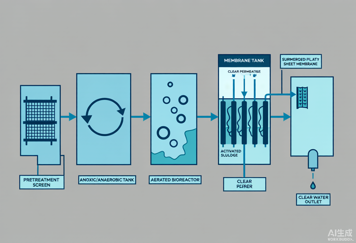
The MBR flow path is straightforward:
- Biological degradation: the wastewater first passes through anaerobic/anoxic/aerobic zones, where microorganisms degrade organics and remove nitrogen and phosphorus — the same as a conventional process;
- Membrane retention: the mixed liquor enters the membrane tank, where under gentle suction the water passes through a membrane on the order of 0.1 μm to become permeate, while the activated sludge is 100% retained and returned to the biological stage, forming a sludge-water loop.
Aeration plays a dual role here: it supplies oxygen to the microorganisms and generates a shearing air flow that scours the membrane surface to delay fouling. Because the membrane holds all the sludge in the system, the MLSS can be raised almost without limit, giving rise to the engineering advantage of a small tank, high concentration and good effluent.
2. Three Core Parameters: Flux, MLSS and Energy Consumption (the Fundamentals of Selection)
A large-scale MBR survey in China (Zhang et al., Engineering 2021, covering dozens of industrial/municipal MBRs) gives the following actual operating ranges for industrial wastewater:
① Membrane Flux — how much water each unit of membrane area produces
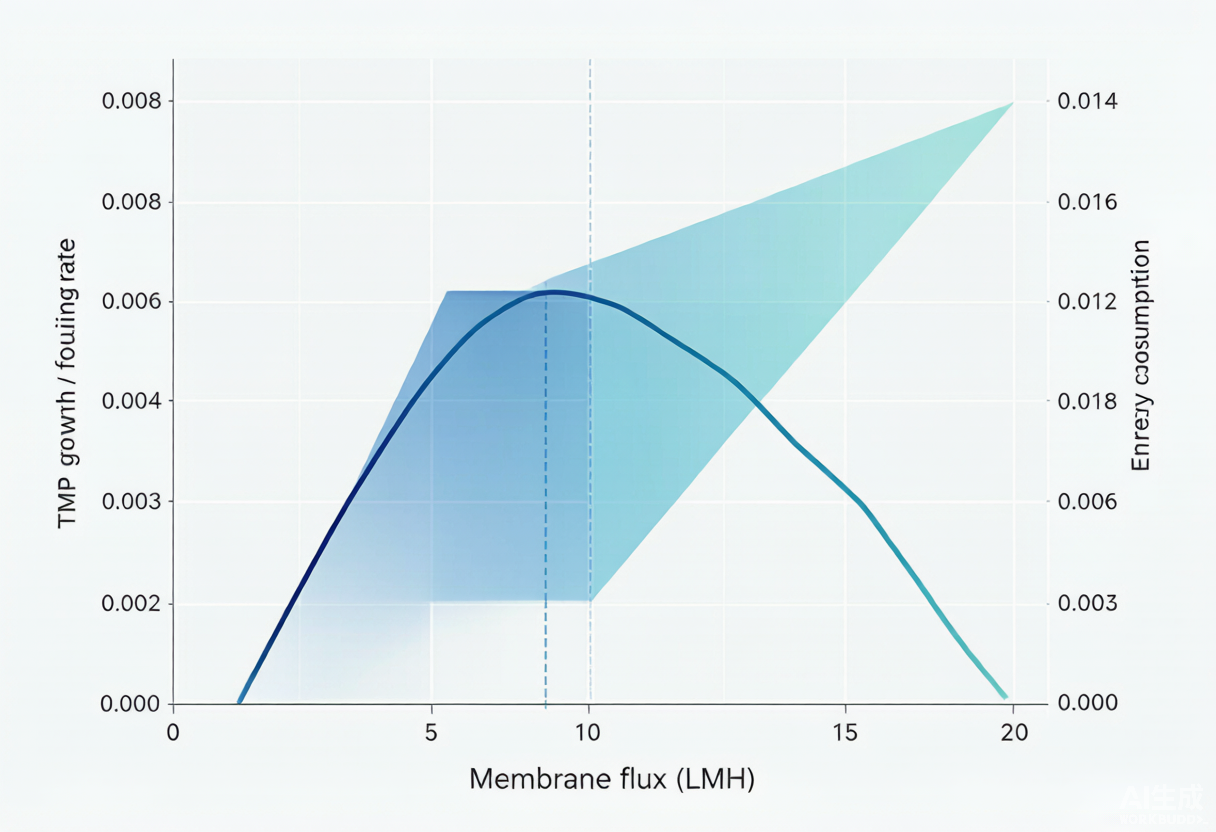
Industrial MBR design flux is typically 15–25 LMH (L/m²·h), with an actual average of about 15.9 LMH. But higher is not always better: a higher flux saves membrane area and lowers capital cost, yet the fouling rate and aeration energy rise in tandem. Several project reports note that once flux exceeds 18–20 LMH, the TMP (transmembrane pressure) rises markedly faster.
② MLSS (Sludge Concentration) — how concentrated the biological tank can run
Measured MLSS in industrial MBRs is mostly 8–12 g/L (average 10.3 g/L), 3–5 times that of a conventional process. This high concentration delivers a high volumetric loading (e.g., a papermaking MBR reaches 3.2 kgCOD/(m³·d), 2.3 times the activated sludge process) and a much smaller footprint.
③ Energy Consumption — Aeration Is the Biggest Share
A modern industrial MBR consumes about 0.3–0.7 kWh/m³ per tonne of water (aeration + suction), and very large installations can push this down to 0.3–0.5 kWh/m³. Because municipal/reuse scenarios include tertiary treatment, conventional processes also need 0.6–1.2 kWh/m³ — the two are now close. In the Kubota submerged pilot, aeration accounts for nearly 50% of total energy — so saving aeration is saving MBR money.
3. Real Project Accounts (All from Published Project Cases)
| Industry / Scale | Process and Key Operating Conditions | Effluent / Removal Performance | Source |
|---|---|---|---|
| Petrochemical wastewater / 2500 m³/d | Submerged MBR (PVDF), MLSS 10500, influent COD 480–1200 | Effluent COD 18–22 mg/L; 0.38 kWh per tonne; treatment cost RMB 1.26 (34% lower than the original SBR); payback 4.2 years | Yangpu ethylene petrochemical MBR project case (2026 technical guide) |
| Wastepaper pulp and papermaking / 2000 m³/d | Hydrolysis acidification + MBR + UF + RO, PVDF flat sheet 0.03 μm, MLSS 10000, flux 16 LMH | Effluent COD 32 mg/L (95.3%); reuse rate 95%; treatment cost RMB 4.0→2.8 per tonne; annual saving about RMB 7.2 million | Papermaking wastewater MBR optimization guide (2024) |
| Waste incineration leachate / 1000 m³/d | Pretreatment + anaerobic IOC + external MBR + NF/RO, MBR-stage MLSS 15 g/L | MBR-stage COD removal ~90%, NH₃-N/TN >97%; overall effluent COD 20–60 mg/L | Everbright Environment, Water Purification Technology 2022 |
| Printing and dyeing wastewater / 2000 m³/d | MBR + RO, PVDF hollow fiber 0.03 μm, flux 10–18 LMH | Overall recovery 85–90%; RO permeate TDS<200, color removal >99%, COD<20; operating cost 0.8–1.5 USD/m³ | TheWay Membranes project case |
| Pharmaceutical wastewater / 60 m³/d | EnviQ submerged flat-sheet PVDF 0.04 μm, flux 16 LMH, MLSS 3000–8000 | Turbidity <1 NTU, stable permeate flow of 3 m³/h since 2022 | QUA EnviQ project case |
4. How to Choose the Membrane: PVDF Flat Sheet vs Hollow Fiber, and PTFE for Tough Duty
Membrane material and configuration are the watershed in MBR selection:
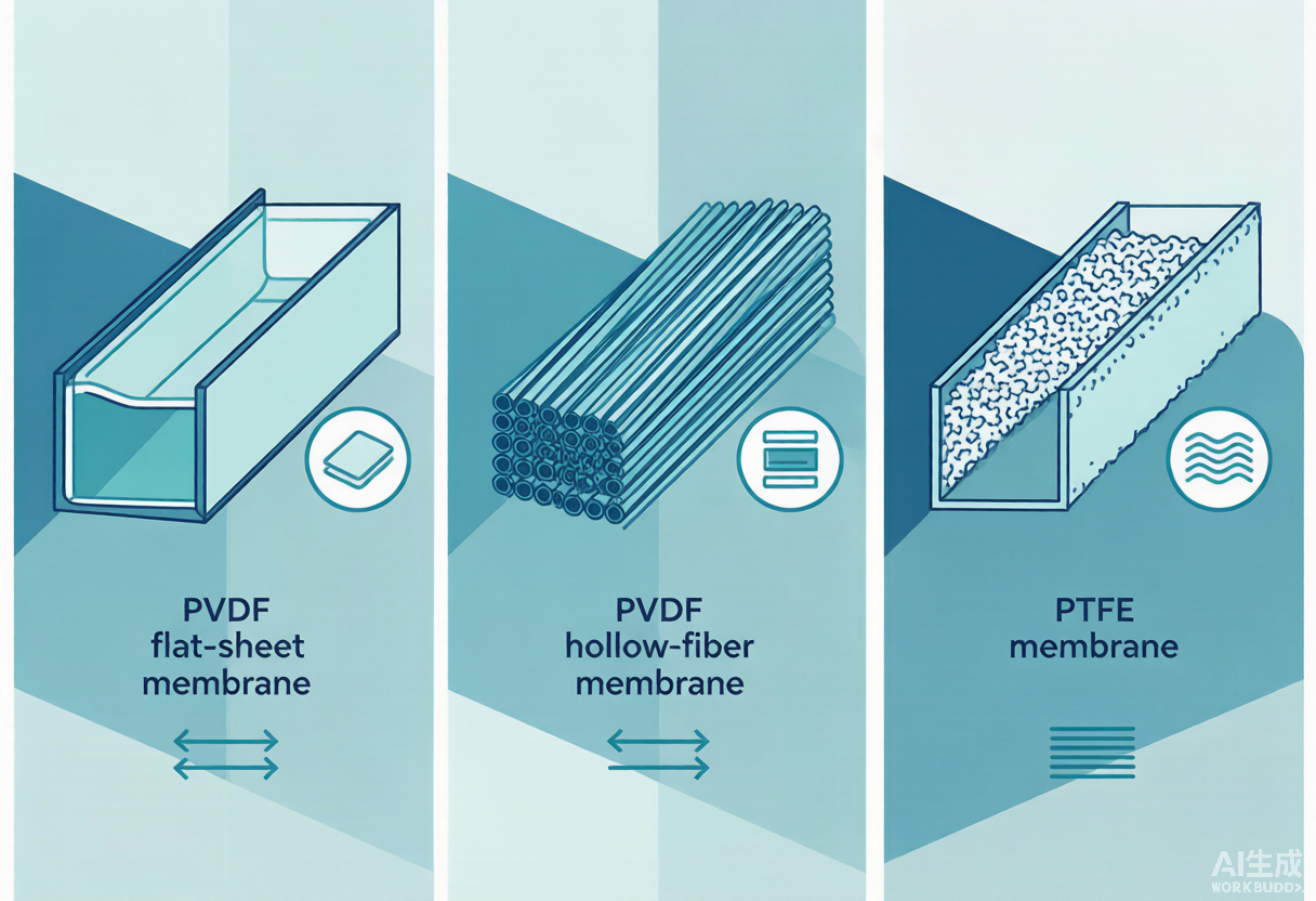
- PVDF (polyvinylidene fluoride): currently the dominant choice — chemical- and heat-resistant with a wide pH range. Flat-sheet modules have wide channels that resist fouling by fibers and grease, allow single-sheet replacement and cost less to maintain, making them the preferred option for food processing, papermaking and printing and dyeing; hollow-fiber modules have high packing density and an initial flux of up to 25–30 LMH, but their narrow channels clog easily and often require whole-module replacement. Industry reports give: flat-sheet energy 0.3–0.5 kWh/m³, hollow-fiber 0.4–0.7 kWh/m³. Even in harsh environments such as printing and dyeing, PVDF can still reach a 5–8 year life.
- PTFE (polytetrafluoroethylene): tougher, longer-lived and higher-flux — the Ningbo leachate case benefits from exactly this. Its downside is cost; it suits high-concentration, hard-to-treat streams that demand a long service life.
Favorable price trend: the price of MBR membrane elements in China has fallen from about RMB 940/(m³·d) in 2013 to about RMB 370/(m³·d) in 2019, and membrane life is generally 4–7 years (about 5 on average) — a key reason MBR has moved in recent years from expensive to affordable.
5. Economics: Membranes Are Costly, but They Save Space, Sludge and Deliver Stable Effluent
- Small footprint: by replacing the secondary clarifier and filter, MBR typically occupies 40%–60% less land than a conventional process — critical where land is scarce or for underground construction (the petrochemical case above cut its footprint by 62%).
- Less sludge: sludge yield of 0.2–0.4 kgTSS/kgCOD, markedly lower than conventional processes; in the petrochemical case the sludge-yield coefficient was only 0.25, cutting hazardous-waste disposal costs by RMB 890,000 a year.
- Operating-cost structure: chemical costs for industrial MBR average about RMB 1.17/(m³·d), roughly 60% of total treatment OPEX (average 1.94) — mainly from maintenance and recovery cleaning chemicals for the membrane.
6. Four Pitfalls Engineering Must Watch Closely
1. Membrane Fouling Is the No. 1 Enemy
A slow TMP rise and flux decline are the norm. The countermeasure is a combined punch: intermittent aeration plus online backwashing (the papermaking case backwashes every 25 minutes) and quarterly recovery chemical cleaning (CIP); aeration intensity must be sufficient to strip the attached layer through turbulent shear (the papermaking case raised aeration to 1800 L/(m²·h) to control fiber fouling).
2. Aeration Accounts for Nearly Half the Energy
As noted, aeration accounts for nearly 50% of total energy. Using jet aeration to push oxygen utilization above 35% and optimizing the air-to-water ratio is the most direct lever for cutting energy.
3. High-Salinity/Reuse Requires Source Segregation + RO
MBR only retains suspended solids and macromolecules and does not remove salt. Reuse applications (especially printing and dyeing and leachate) must be followed by UF + RO; high-TDS brine must be diverted at the source, otherwise both RO recovery and membrane life will be dragged down.
4. Membrane Replacement Is a Hidden Cost
With a life of 4–7 years, replacement accounts for a significant share of O&M. Prefer flat-sheet (single-sheet replacement) over hollow-fiber (whole-module replacement) to save money long term; regular CIP can extend membrane life by 25%–30%.
7. One-Line Selection Advice
Suitable for: industrial wastewater where land is tight, effluent quality must be high and stable (reuse or strict discharge), sludge reduction is desired, and scale is small-to-medium (tens to tens of thousands of m³/d).
Not suitable for: large-flow scenarios that only seek the lowest initial investment, have no reuse requirement and face relaxed discharge limits — there a conventional AO + secondary clarifier is usually more economical. Leave MBR to the hard requirements of reuse and stable effluent.
References (Verified Sources)
- Zhang J, Xiao K, Liu Z, et al. Large-Scale Membrane Bioreactors for Industrial Wastewater Treatment in China: Technical and Economic Features, Driving Forces, and Perspectives. Engineering, 2021, 7:868–880 (doi:10.1016/j.eng.2020.09.012).
- Technical Guide for the Wastewater Treatment Plan of Danzhou Yangpu Economic Development Zone (2026 Optimized Edition) — an MBR treatment case at a petrochemical enterprise. wateretechs.com.
- MBR Membrane Bioreactor Treatment of Papermaking Wastewater: Guide to 300 nm Pore-Size Optimization and Measured Per-Tonne Cost (2024). wateretechs.com.
- Chen J, Xiao C, Gui H, et al. Engineering case of leachate treatment at a municipal solid waste incineration power plant [J]. Water Purification Technology, 2022, 41(3):100-103,109.
- TheWay Membranes. MBR for Textile Wastewater: Color Removal & Reuse.
- QUA. EnviQ® Submerged MBR at a Leading Pharma Company (case study, since 2022).
- Bouhabib B, et al. Monitoring and analysis of the energy cost of an MBR (Kubota pilot, Spain). Desalination, 2009 (doi:10.1016/j.desal.2009.06.018).