



 Nationwide (dyeing, fine chem, pharma, food, municipal upgrade)
 Pilot to full-scale (100s–10,000s m³/d)
Biological Aerated Filter (BAF): Squeezing "Biofilm + Filtration" into One Tank — a Compact Powerhouse for Industrial Wastewater Advanced Treatment
Conventional activated sludge relies on a secondary clarifier to separate sludge from water by settling; BAF's idea is to pack biofilm oxidation and physical filtration into a single tank — small media granules carry a dense biofilm, so wastewater is both biodegraded and retained as it passes through the media bed. Drawing on CECS 265—2009, GB 50684—2011 and real engineering records from printing and dyeing, fine chemicals and other sectors, this article explains media, loading, backwashing and selection in one place.
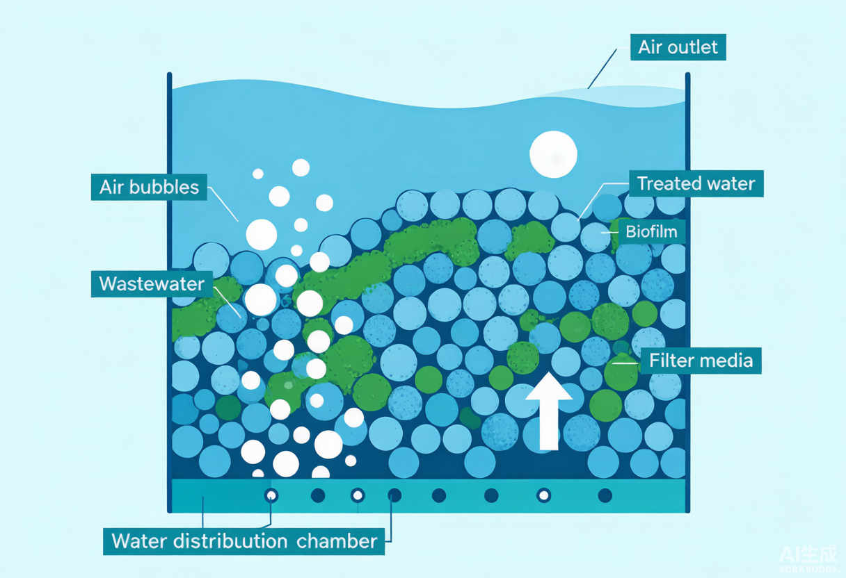
1. Principles: Media-Attached Biofilm Plus Upflow Aeration — One Film, Three Jobs
A typical BAF runs in upflow mode: water and air are introduced at the bottom, wastewater flows upward through the media bed, and clarified water is collected at the top. The biofilm attached to the media surface performs organic matter degradation and nitrification; because the biofilm is relatively thick and oxygen diffusion from the outer layer inward is limited, anoxic/anaerobic micro-zones form inside the film, enabling simultaneous nitrification-denitrification in a single reactor. Meanwhile, the voids between media granules physically retain SS and sloughed biofilm fragments, so effluent suspended solids are usually very low.
In engineering practice, BAFs are commonly divided into four types:
- C/N filter (carbon oxidation/nitrification): removes organic matter while oxidizing part of the ammonia nitrogen to nitrate;
- N filter (nitrification): focuses on ammonia nitrification and requires the influent BOD₅ not to be too high (GB 50684 recommends no more than 30 mg/L);
- DN filter (denitrification biofilter): operates without aeration or with only micro-aeration and doses a carbon source to reduce nitrate to nitrogen gas;
- Combined configuration: commonly a two-stage "C/N + N" arrangement, or "DN + C/N" with recirculation, to meet COD, ammonia nitrogen and total nitrogen limits simultaneously.
The key here is load matching: if the organic loading on the C/N filter is too high, heterotrophic bacteria will outcompete nitrifiers and lower ammonia nitrogen removal. When strict effluent ammonia nitrogen limits apply, carbon oxidation and nitrification are therefore usually placed in two separate stages, or a hydrolysis acidification/anaerobic stage is installed ahead of the BAF to remove most of the COD first.
2. Key Parameters: Loading, Media and Backwashing Are the "Iron Triangle" of Sizing
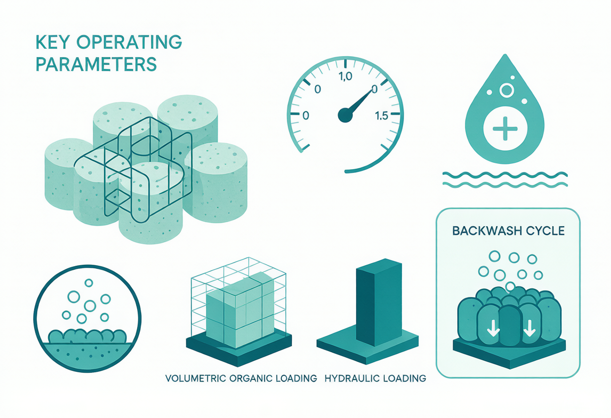
BAF design parameters are clearly recommended in CECS 265—2009 and GB 50684—2011. The core logic: loading determines removal capacity, media determines biomass and retention efficiency, and backwashing determines the operating cycle and energy consumption.
① Media: Ceramsite vs. Volcanic Rock
Heavy media should be volcanic rock or sintered clay ceramsite in a single uniform layer; media size is 3–5 mm for carbon oxidation/nitrification and preferably 4–6 mm for denitrification; media bed depth is 2.5–4.5 m with a 300–350 mm gravel support layer at the bottom. Commercial literature often emphasizes a specific surface area of ≥300 m²/m³ (or ≥5 m²/g) to ensure adequate biofilm attachment; biofilm concentration can reach 10–15 g/L. Media material and particle size directly affect the clogging cycle and backwash frequency.
② Loading and Filtration Rate
As an advanced treatment unit, the filtration rate is generally 2–6 m³/(m²·h); the carbon-oxidation BOD₅ volumetric loading is 2–6 kg/(m³·d) (GB 50684 gives 2–4, CECS gives 3–6; the overlap is the commonly used range); nitrification loading is 0.3–0.8 kg NH₃-N/(m³·d); and denitrification loading is 0.8–4.0 kg NO₃-N/(m³·d). The empty-bed hydraulic retention time of a denitrification filter should be 20–30 min.
③ Aeration and Backwashing
In the aerobic zone, DO is controlled at 2–4 mg/L; in the denitrification zone, DO ≤0.5 mg/L. The air-to-water ratio is commonly 1:1–3:1, though some engineering references give 3:1–5:1 and it must be calculated from the actual oxygen demand. Backwashing follows three steps — "air scour → combined air-water wash → clean water rinse": air scour intensity 10–15 L/(m²·s), water wash 4–8 L/(m²·s), cycle 24–72 h, with backwash water accounting for about 3%–10% of product water. Influent SS must be kept below 60 mg/L, and a 1–2 mm fine screen should be installed upstream.
These parameters are not independent: the smaller the media particle size and the larger the specific surface area, the higher the biomass that can be carried, but clogging and backwash frequency also rise; the higher the filtration rate, the smaller the footprint, but the shortened hydraulic retention time lowers removal efficiency. In engineering, a trade-off must be struck among footprint, investment and operating cycle.
3. Real Engineering Records (All from Public Literature and Industry Reports)
| Industry / Scale | Process and Key Conditions | Effluent / Removal Performance | Source |
|---|---|---|---|
| Combined wastewater from a printing and dyeing industrial park | Hydrolysis acidification + contact oxidation + BAF; influent COD 800 mg/L, BOD₅ 250 mg/L | Effluent COD<60 mg/L, BOD₅<20 mg/L; COD/BOD₅ removal>92%; meets GB 18918—2002 Grade 1-B | Lu Xujie et al. China Water and Wastewater, 2008; Xiang Song et al. Industrial Water Treatment, 2013 (cited) |
| A fine chemical industrial park in northwest China / 4000–6000 m³/d | Iron-carbon micro-electrolysis - Fenton - hydrolysis acidification - Bardenpho - secondary clarifier - magnetic coagulation - ozone - BAF - deep-bed denitrification filter | BAF ensures effluent COD<30 mg/L; the deep-bed denitrification filter takes TN from 20 to <15 mg/L; unit treatment cost about RMB 7.45/m³; effluent approaching Class IV surface water quality | Water Supply and Drainage Technology Network (gxshuixie.com) industry report |
| Guangdong Esquel Textiles advanced reuse / 5000 t/d | Integrated ozone-BAF; operated for about 1 year, cumulative treatment of 1.8 million tonnes | COD 100→40 mg/L, color 100→<20 times; per-tonne operating cost RMB 0.5–1 lower than activated carbon/physicochemical processes; annual COD reduction of over 400 tonnes | Textile Science and Technology Network (tex.org.cn) industry-academia report |
| BAF project at Xianyang West Suburb WWTP | Ceramsite media seeded for biofilm attachment, successful startup in 30 d; stable compliance with influent COD<200 mg/L | When influent COD exceeds 250 mg/L, effluent COD and SS cannot meet limits stably; at FeCl₃ β=2.2, phosphorus removal 89.5%, SS 97.4%, COD 49.6%; with 80 mg/L FeCl₃, effluent TP<1.0 mg/L | Master's thesis, Xi'an University of Architecture and Technology (search.napstic.cn) |
| MSG plant high-carbon, high-nitrogen wastewater / 8000 m³/d | Ammonia nitrogen still exceeded limits after UASB + contact oxidation; hydrolysis acidification - upflow BAF - modified BAF, HRT 18 h | Influent COD 600–1000, NH₄⁺-N 350–500 → effluent COD 30–50, NH₄⁺-N 3–5 mg/L, meeting circulating cooling water reuse standards | Patent CN101698557A |
A pattern emerges from these engineering records: BAF performs most reliably in "low-concentration, biodegradable, pre-treated" scenarios. In the printing and dyeing industrial park, after hydrolysis acidification and contact oxidation, the BAF mainly handles the final carbon oxidation and SS retention; in the fine chemical park it is placed after ozone to degrade the small biodegradable organics produced by ozone chain scission. Conversely, when influent COD exceeds 250 mg/L or SS is high, BAF tends to be caught between throughput and backwashing.
4. Process Positioning: Where BAF Sits in the Biological Treatment Spectrum
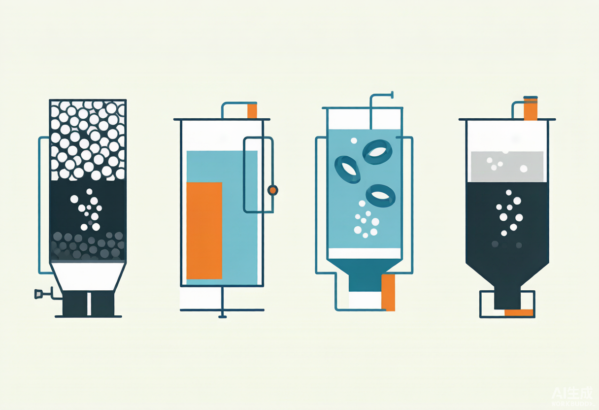
Compared with the biological processes covered previously, BAF's core positioning is a "compact integrated biological filtration unit": unlike UASB, which targets high-concentration anaerobic methanogenesis; unlike MBR, which uses a membrane to retain sludge at high concentration; and unlike MBBR, which lets carriers move freely within the tank. BAF is more like a "rapid filter loaded with microorganisms", suited as an advanced treatment step after secondary treatment, or as an integrated biological + filtration unit for small- to medium-scale industrial wastewater.
| Comparison Item | BAF | MBR | MBBR | UASB |
|---|---|---|---|---|
| Core function | Biofilm oxidation + filtration retention | Biological treatment + membrane separation | Suspended-carrier biofilm | Anaerobic methanogenesis + degradation of high-strength organics |
| Secondary clarifier required | Usually not required | Not required | Usually required | Requires three-phase separation |
| SS retention | Strong (media bed) | Very strong (membrane filtration) | Weak (carriers follow water) | Weak |
| Footprint | Small | Very small | Relatively small | Medium |
| Typical position | Advanced treatment / small-medium scale integration | Reuse / high-standard effluent | Upstream biological treatment or capacity expansion retrofit | Anaerobic stage for high-strength organic wastewater |
| Main energy consumers | Aeration + backwashing | Aeration + suction pumps | Aeration + mixing | Heating/insulation + biogas utilization |
5. Selection Guidance and Common Engineering Pitfalls
Where BAF fits: tight sites that need simultaneous biological degradation and SS retention; advanced treatment after secondary effluent or standard-upgrade retrofits; small- to medium-scale industrial wastewater (hundreds to tens of thousands of m³/d) with reasonable biodegradability and controllable SS. Printing and dyeing, food processing, pharmaceutical and municipal WWTP upgrade projects are all common applications.
Where BAF is not ideal: high-strength organic wastewater fed directly to BAF is often overwhelming — operating experience at the Xianyang West Suburb WWTP shows that when influent COD exceeds 250 mg/L, effluent COD and SS struggle to meet limits stably, so high-strength wastewater should first pass through anaerobic treatment or hydrolysis acidification. In winter, when water temperature drops below 12°C, nitrification slows markedly, requiring covers and insulation, reduced loading, or extended HRT. When total phosphorus limits are strict, BAF's own biological phosphorus removal is limited, and chemical phosphorus removal must be added.
Four Pitfalls Engineering Must Watch Closely
- 1. Influent SS is the lifeline: CECS 265—2009 specifies that influent SS should be below 60 mg/L; otherwise clogging drastically shortens the backwash cycle. A fine screen or sedimentation must be installed upstream.
- 2. Overly strong backwashing strips the biofilm: air scour intensity of 10–15 L/(m²·s) and water wash of 4–8 L/(m²·s) are the usual ranges. Excessive backwashing washes away active biofilm and actually worsens effluent quality.
- 3. Get the denitrification carbon dose right: GB 50684 recommends estimating the external carbon source at 3–5 times the nitrate nitrogen concentration to be removed (as CODcr); too little carbon means TN cannot meet the limit, while too much causes COD rebound.
- 4. The low-temperature nitrification cliff: for every 10°C drop in water temperature, the biological reaction rate roughly halves; winter nitrification loading must be lowered or insulation measures adopted.
References (Real Sources)
- China Association for Engineering Construction Standardization. CECS 265:2009 Technical specification for biological aerated filter engineering [S]. 2009.
- Ministry of Housing and Urban-Rural Development of the PRC. GB 50684—2011 Code for design of wastewater treatment and reuse in chemical industry [S]. 2011.
- Lu Xujie, Sun Rui, Liu Lin, Chen Jihua. Treatment of knitted printing and dyeing wastewater by hydrolysis acidification / contact oxidation / biological filter process [J]. China Water and Wastewater, 2008, 24(22):60-62.
- Xiang Song, Xu Lezhong, Li Cuimei, Guo Yongfu, Chu Jinyu. Treatment of combined printing and dyeing wastewater by hydrolysis acidification — A²/O — biological aerated filter process [J]. Industrial Water Treatment, 2013, 33(5):25-28.
- A combined treatment method for high-carbon, high-nitrogen wastewater: China, CN101698557A [P]. 2010.
- Centralized wastewater treatment project of a fine chemical industrial park in northwest China under high discharge standards [EB/OL]. Water Supply and Drainage Technology Network (gxshuixie.com).
- Pilot results of the integrated ozone — biological aerated filter treatment method at Pacific Textiles [EB/OL]. Textile Science and Technology Network (tex.org.cn).
- Engineering application study of the biological aerated filter process in wastewater treatment plants [D]. Master's thesis, Xi'an University of Architecture and Technology (search.napstic.cn).