


 National Multi-Industry (Printing and Dyeing / Pharmaceutical / Coking / Chemica
 Pilot-scale to full-scale engineering (from tens to tens of thousands of m³/d)
Activated Carbon Adsorption (GAC/PAC): "Catching" the Refractory Organics That "Slip Through" in Biological Effluent
The biological tank can consume most organic matter, but it often "fails to digest" refractory substances such as printing and dyeing dyes, pharmaceutical intermediates, and coking heterocyclic aromatic hydrocarbons. Activated carbon adsorption is not a replacement for biological treatment, but rather a "safety net" for it — using its enormous specific surface area and controllable pore size to intercept residual COD, color, and micropollutants, enabling the effluent to meet discharge or even reuse standards.
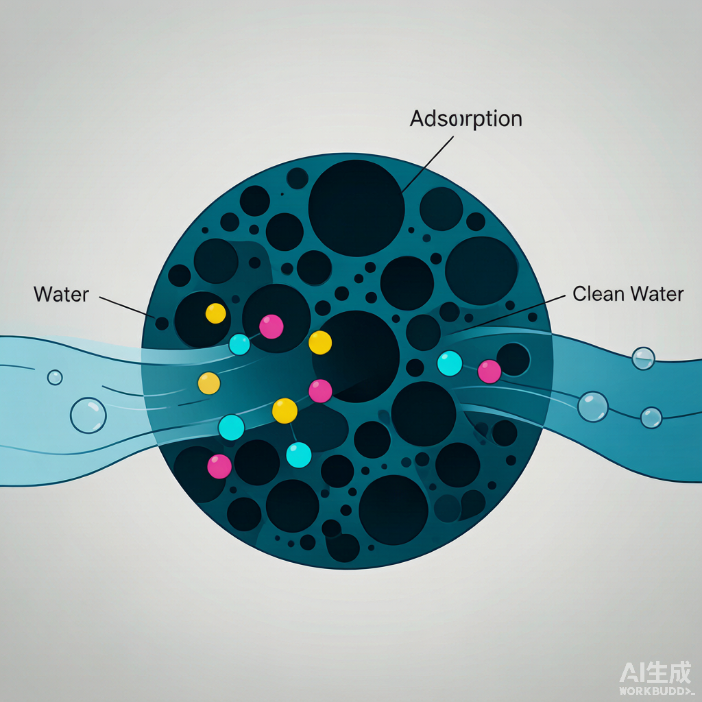
1. Principle: Not a Chemical Reaction, but "Pore Capture"
The backbone of activated carbon consists of turbostratic graphite microcrystals, which, after activation, develop an enormous specific surface area (commercial carbons with iodine values of 950–1050 mg/g typically exhibit BET specific surface areas in the range of 900–1200 m²/g). The adsorption driving force is primarily van der Waals forces, imparting high affinity for aromatic compounds, chlorinated/brominated organics, dye molecules, phenols, antibiotics, and similar substances.
The adsorption process proceeds in three steps: ① External diffusion — pollutants traverse the liquid film to reach the carbon external surface; ② Internal diffusion — pollutants migrate along the pore channels into the interior of the carbon particle; ③ adsorption at active sites on the pore walls. In engineering practice, due to mixing intensity, contact time, and competition from background organics, the actual working adsorption capacity is often only 25%–50% of the equilibrium capacity determined from bench-scale isotherm tests (as recommended by the Metcalf & Eddy design manual) — this is the reason design must apply a safety factor.
2. How to Choose Between GAC and PAC
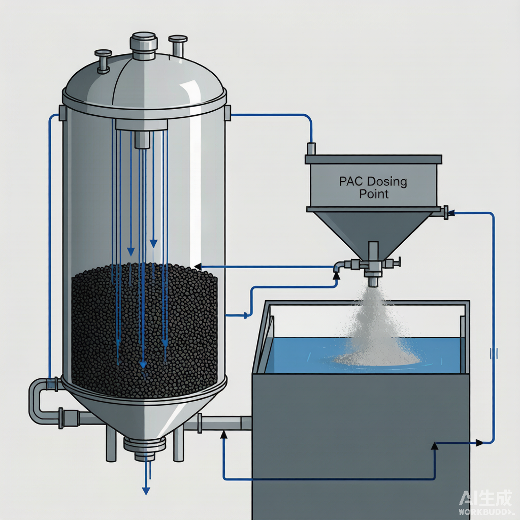
The two are not in competition but are tools for different scenarios. PAC acts like an "emergency remedy," while GAC serves as a "long-term guardian."
| Comparison Item | PAC (Powdered Activated Carbon) | GAC (Granular Activated Carbon) |
|---|---|---|
| Particle Size | Tens to hundreds of microns | 0.8–1.6 mm (commonly 8×30 mesh) |
| Dosing/Application Mode | Directly dosed into biological tank/sedimentation tank/reactor | Packed in fixed-bed adsorption columns/filters |
| Typical Dosage/EBCT | 10–200 mg/L, depending on water quality and shock loading | EBCT 15–30 min (micropollutants), BAC ≥15–30 min |
| Regeneration | Mostly discharged with sludge; essentially non-regenerable | Thermally regenerable 3–5 times, recovering 80%–95% iodine number |
| Suitable Scenarios | Water quality shocks, emergency compliance, seasonal color events | Long-term advanced treatment, reuse, stable micropollutant removal |
A typical combination is "PAC for emergency + GAC/BAC for long-term": a chemical industrial park case shows that when MBR effluent COD spikes periodically, PAC at 100–200 mg/L can reduce effluent COD from 80–120 mg/L to below 55 mg/L; after stable operation, switching to a GAC system can cut annual operating costs from approximately 96万 RMB (continuous PAC dosing) to about 35万 RMB (including thermal regeneration)—a significant economic difference (source: industry engineering reports, [To be verified]).
III. Key Design Parameter: EBCT is the Core
The most frequently underestimated parameter in GAC system design is the Empty Bed Contact Time (EBCT). A systematic study published in Water Research 2020年 (on micropollutant removal from municipal wastewater) indicated that, regardless of activated carbon type, the EBCT required for stable micropollutant removal typically ranges from 20–30 min; an excessively short EBCT wastes adsorption capacity, while an overly long one is uneconomical. For industrial wastewater, due to higher organic matter concentrations, the design EBCT is often set at 15–30 min, with the specific value to be determined through pilot-scale or on-site trials.
Other Engineering Control Points
- Iodine Number and Pore Size: For printing and dyeing wastewater decolorization, prioritize carbons with high methylene blue value and well-developed mesopores; for pharmaceutical/ drinking water micropollutant removal, prioritize coconut shell carbons with iodine number ≥1000 and well-developed micropores.
- pH: Acidic conditions favor the adsorption of heavy metal ions (less H⁺ competition); neutral to weakly acidic conditions (pH 6–7) are generally favorable for the physical adsorption of most organic compounds.
- Temperature: Moderate temperature increase (25–40 ℃) accelerates diffusion, but excessively high temperatures reduce the equilibrium adsorption capacity.
- Pretreatment: Influent SS and oils/grease must be controlled; otherwise, carbon pores are quickly blocked, significantly shortening the adsorption cycle.
IV. Real-World Engineering Cost-Benefit Analysis
The following case studies synthesize peer-reviewed literature and industry engineering reports; data from commercial sources are marked with [To Be Verified] in the table and are recommended for manual review prior to publication.
| Industry / Scale | Process & Key Operating Conditions | Effluent / Removal Performance | Source / Reliability |
|---|---|---|---|
| Coking wastewater / Pilot-scale | BAC tower, empty bed contact time 4 h, biofilm developed with highly efficient coking-degrading bacteria | Influent COD averaging approx. 120 mg/L → effluent <60 mg/L, average removal rate >50%; UV254 removal rate >70% | Li Jin et al., Industrial Water Treatment, 2015 (CNKI GYSC201509019) |
| Biologically treated coking effluent / Pilot-scale | GAC/UV/O₃ synergistic catalytic oxidation, O₃ 30 mg/L, UV 630 mJ/cm², saturated GAC dosing | COD 100–130 → 60–78 mg/L, removal rate 40.7%; meets expected industry standards | Wu Chunxu et al., Environmental Protection Science, 2020, 46(2):35-38 |
| Pharmaceutical wastewater / 60 m³/d | Columnar coconut-shell activated carbon, iodine value ≥1000, 8×30 mesh, 3-stage series, total contact time 60 min, air-to-water ratio 3:1, quarterly thermal regeneration | After pretreatment + Fenton, COD 4500 → effluent COD ≤50 mg/L; single-stage COD removal 65%–75%, three-stage total ≥85%; continuous operation for 3年 without breakthrough | Industry engineering case (7zhongcarbon) [To be verified] |
| Printing and dyeing plant in Guangdong / Not disclosed | Dual-column series coal-based GAC, EBCT 25 min, pH 6.5–7.0, iodine value ≥950, methylene blue ≥200 mg/g | Secondary biological effluent COD 300–400 → 50–75 mg/L, color reduced to <50×; carbon service life approx. 4 months, thermal regeneration restores approx. 82% | Industry engineering guide (sinotechcarbon) [To be verified] |
| Pharmaceutical wastewater in Germany / Continuous 2年 | GAC fixed bed, online UV254 monitoring, thermal regeneration of saturated carbon | Influent COD 95–110 → 18–25 mg/L, average removal 78%; 6 pharmaceutical compounds all <0.01 μg/L; regenerated carbon restores 94% iodine value | Industry case study (YICARB) [To be verified] |
| Synthetic pharmaceutical wastewater / Batch test | Multi-component pharmaceutical wastewater, initial TOC 911.8 mgC/L, 23 ℃, Langmuir nonlinear fitting | Maximum monolayer adsorption capacity qmax≈47 mgC/gAC; Freundlich nF=0.28, indicating unfavorable adsorption at low concentrations | MDPI Water, 2024, 16(15):2086 |
| Dyes / Batch test | Shell-based activated carbon, methylene blue (MB)/ofloxacin (OFL), 298 K | MB adsorption fits Langmuir model (R²>0.99), rapid within 2 h, equilibrium at 24 h, removal rate >90% | MDPI Water, 2022, 14(22):3752 |
V. Regeneration: The Key Step to Making GAC Affordable
The greatest advantage of GAC is its regenerability. Mainstream thermal regeneration is carried out at 800–900 ℃ under oxygen-deficient or steam-blanketed conditions: first, drying at 100–150 ℃, then carbonization of organics at 300–700 ℃, and finally pore activation at 800–900 ℃. A single thermal regeneration cycle can restore 80%–95% of adsorption capacity, but is accompanied by 5%–15% carbon burn-off loss; typically, it can be recycled 3–5 times, extending the overall service life to 2–5年. PAC, being mixed with sludge, is essentially treated as a single-use consumable.
Chemical regeneration (acid, alkali, or solvent soaking) is suitable for heavy metals or specific organic compounds, with a recovery rate of approximately 60%–80%, and can generally only be repeated 2–3 times; steam regeneration is suitable for low-boiling-point organics and can be repeated 5–8 times, but has limited effectiveness for high-boiling-point pollutants. In engineering practice, only 3–5 tons of saturated carbon makes it worthwhile to send to a specialized regeneration facility for centralized processing; if the volume is too small, direct replacement with fresh carbon is more economical.
VI. 4 Pitfalls That Engineering Must Watch Out For
1. Treating Activated Carbon as a "Cure-All"
Activated carbon performs poorly in adsorbing hydrophilic substances such as small-molecule organic acids, alcohols, and sugars. A water quality analysis must be conducted first to confirm whether the target pollutants are hydrophobic/adsorbable substances such as aromatics, heterocyclics, dyes, or antibiotics, before deciding whether to use carbon.
2. Overly Short EBCT Design
Compressing the EBCT below 5 min to save equipment costs often results in "water passing through faster than pollutants can enter the pores," leading to rapid breakthrough in the effluent. Metcalf & Eddy clearly states: engineering design capacity should be divided by a safety factor (typically 4 times) based on bench-scale isotherm data.
3. Inadequate Pretreatment
Influent SS and oil >10 mg/L will clog carbon pores, causing irreversible fouling. Filtration/coagulation-sedimentation/DAF must be installed upstream. As a rule of thumb, turbidity entering the GAC should be controlled at a low level, with a backwash cycle of 24–72 h.
4. Missing Saturation Monitoring
Without online UV254 or effluent COD monitoring, activated carbon may already be exhausted while the system continues operating. It is recommended to install an online UV254 analyzer downstream of the GAC, establish a breakthrough curve, and determine carbon replacement/regeneration based on dual parameters of "treated water volume + effluent indicators."
VII. Process Positioning and Selection Recommendations
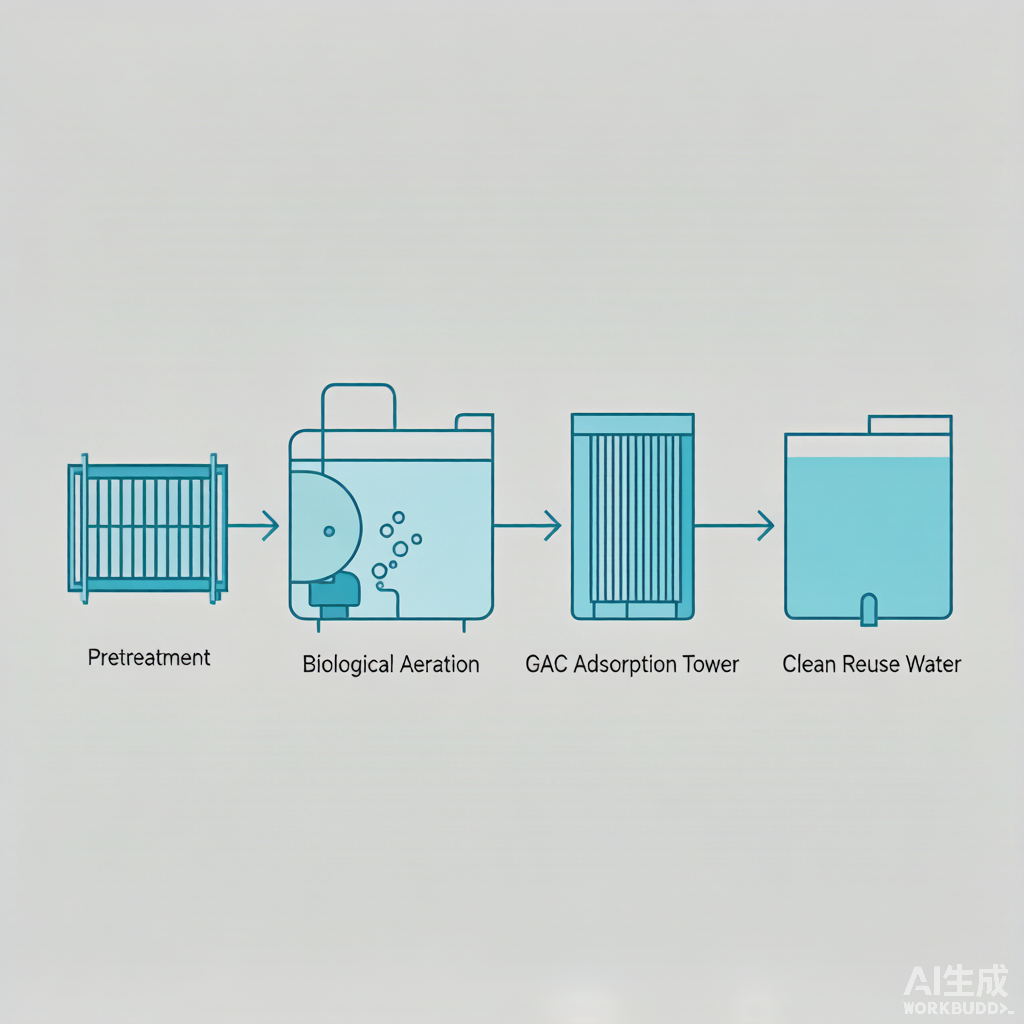
The optimal position for activated carbon adsorption in industrial wastewater treatment is the polishing stage, after biological treatment and before reuse. It cannot replace biological treatment or advanced oxidation, but it can efficiently capture refractory organics and color that remain after biological/oxidation processes.
Suitable for: Scenarios in printing and dyeing, pharmaceutical, coking, and chemical industrial parks where effluent COD/color from biological treatment fails to meet standards, or where water reuse is required (RO upstream protection).
Not suitable for: Plants where influent COD consists primarily of biodegradable small molecules and there is no requirement for polishing treatment/reuse — in such cases, enhancing biological treatment should be the priority, and using activated carbon would add unnecessary OPEX.
References (Verified Sources)
- Ruhl A. S., et al. Empty bed contact time: The key for micropollutant removal in activated carbon filters. Water Research, 2020, 116765 (doi:10.1016/J.WATRES.2020.116765).
- Sarioglu O. F., et al. Adsorption of a Multicomponent Pharmaceutical Wastewater on Charcoal-Based Activated Carbon: Equilibrium and Kinetics. Water, 2024, 16(15):2086 (MDPI).
- Study on the Application of Shell-Activated Carbon for the Adsorption of Dyes and Antibiotics. Water, 2022, 14(22):3752 (MDPI).
- Li Jin, Wang Guanghua, Li Wenbing, et al. Pilot-scale study on advanced treatment of coking wastewater by biological activated carbon technology[J]. Industrial Water Treatment, 2015(9):19. (CNKI GYSC201509019)
- Wu Chunxu, Wu Zheru, Wang Hongying, et al. Synergistic catalytic oxidation for advanced treatment of biochemical effluent from coking plants[J]. Environmental Protection Science, 2020, 46(2):35-38.
- Metro Vancouver. Guidance Document: Adsorption with Granular Activated Carbon — Design Criteria for Fixed Bed Columns, 2013.
- Metcalf & Eddy, Inc. Wastewater Engineering: Treatment and Reuse. 4th ed. McGraw-Hill, 2004. (Field working capacity is 25%–50% of the isotherm equilibrium capacity)
- Weber W. J. Jr. Adsorption processes. Pure and Applied Chemistry, 1974, 37(3):375–392.
- Treatment of industrial wastewater by activated carbon adsorption technology[J/OL]. Environmental Protection Online Industry Technical Article, 2019-04-25. (Saponin/PAC+UF review data)
- How to Reduce COD in Wastewater with Activated Carbon: Complete Engineering Guide. Sinotech Carbon, 2024. (Guangdong printing and dyeing/chemical industrial park case, [To be verified])
- Pharmaceutical wastewater treatment - activated carbon treatment maintained good water quality for three years. Qizhong Carbon official website engineering case, [To be verified].
- Activated Carbon in Wastewater Treatment: Achieving Compliance through Advanced Adsorption. YICARB, [To be verified].