


 Across multiple industries nationwide (power, petrochemical, printing and dyeing
 Pilot-scale to full-scale implementation (from hundreds to tens of thousands of
 Reverse Osmosis (RO) Membrane-Based Advanced Reuse of Industrial Wastewater: Using a Semi-Permeable Membrane to "Sieve" Out Dissolved Salts, Pushing Reuse Rates to 70%–95%
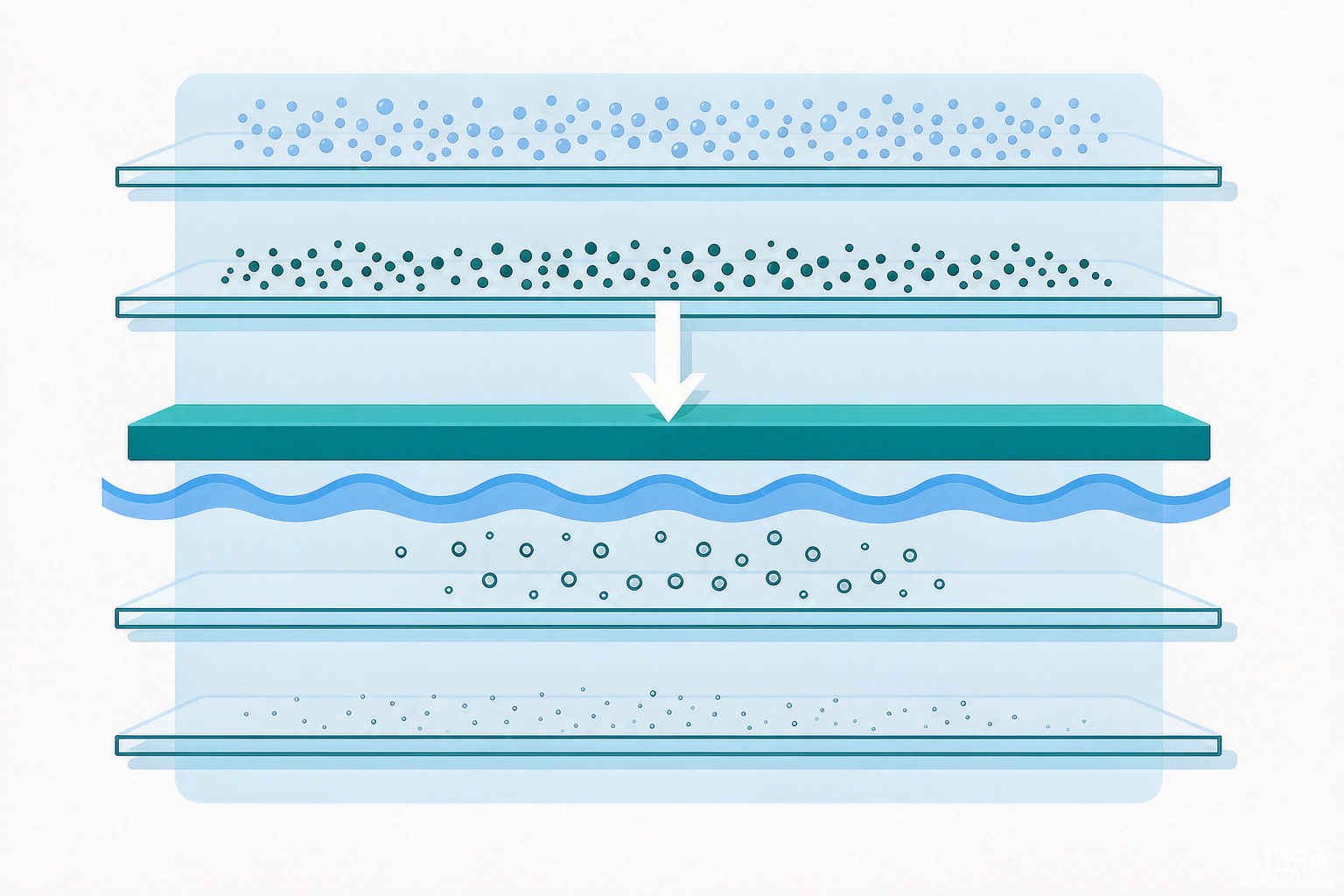
Conventional reuse relying on "sedimentation + filtration" can only remove suspended solids, leaving salts completely untouched. Reverse Osmosis (RO), using a polyamide semipermeable membrane and a high-pressure pump, rejects dissolved salts, small-molecule organics, and color in a single pass, producing water with TDS as low as tens of mg/L—directly reusable for cooling, rinsing, dyeing, and even boiler feedwater. Drawing on multiple peer-reviewed journal articles and real engineering cost ledgers, this article lays out operating pressure, flux, recovery rate, salt rejection, and concentrate disposal in one go.
1. Principle: "Squeezing" Water Through the Membrane Against Osmotic Pressure
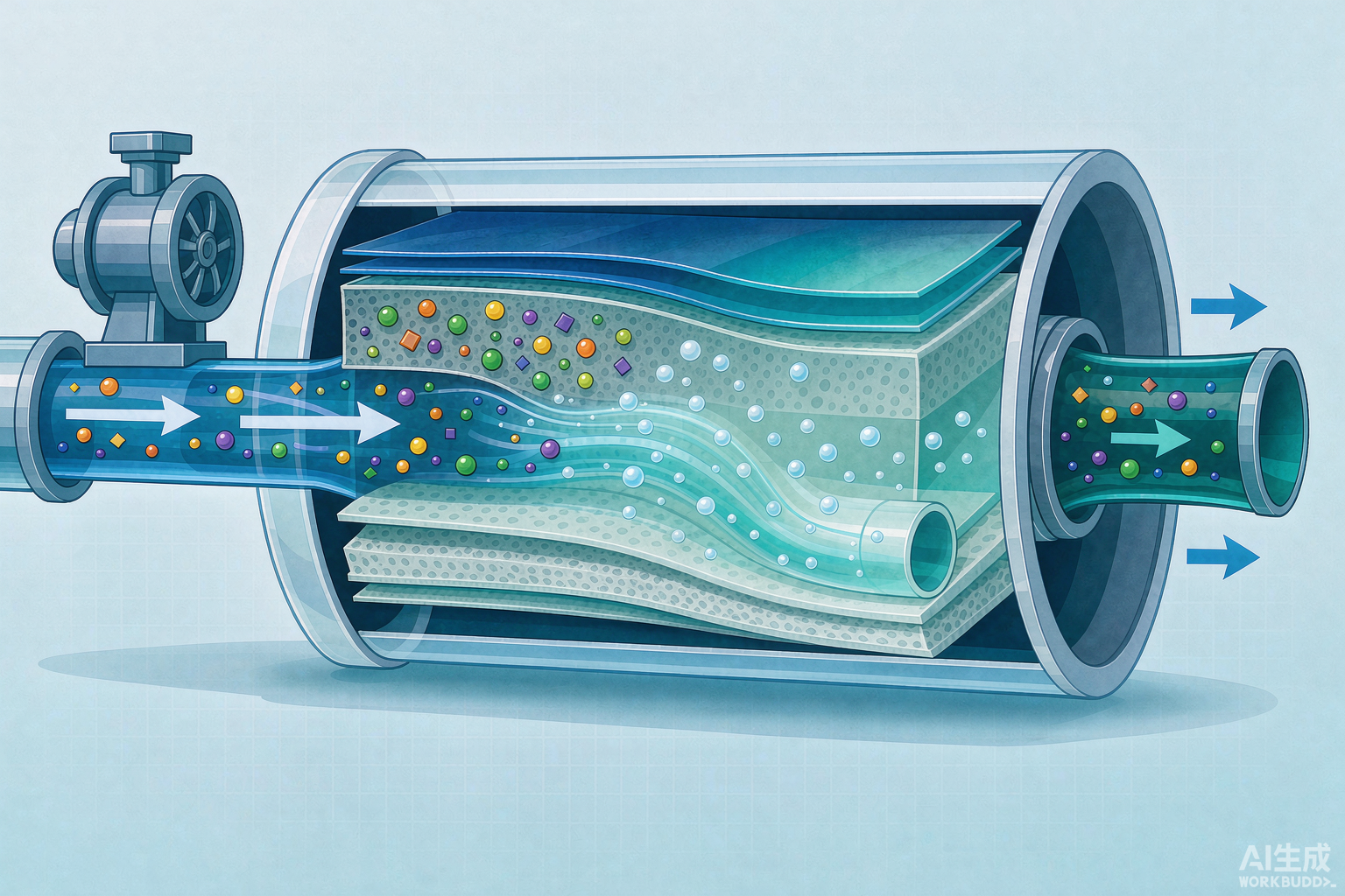
Natural osmosis is the spontaneous flow of water from a dilute solution to a concentrated one; reverse osmosis works the opposite way—by applying pressure to the feed side greater than the osmotic pressure of the concentrate, water is forced to permeate in reverse through the semipermeable membrane to become permeate, while ions and organics are 100% rejected and discharged with the concentrate. What determines whether water can be "squeezed" through is the net driving pressure NDP = feed pressure − osmotic pressure − permeate backpressure − concentration polarization loss. Key rule: the higher the feed salinity, the greater the osmotic pressure, and the higher the pressure required. Seawater with 35 g/L TDS has an osmotic pressure of approximately 28 bar, so seawater RO must operate at 55–70 bar; brackish water at 1k–10k mg/L has a much lower osmotic pressure, where 1.0–2.5 MPa is sufficient.
In practice, the industry uses spiral-wound polyamide TFC composite membranes (8 -inch diameter, 40 -inch long, with 6–7 elements per pressure vessel), where the dense skin layer is responsible for salt rejection and the porous support layer for water permeability. Note that polyamide is "sensitive" to residual chlorine—concentrations as low as 0.1 ppm can cause irreversible membrane damage, so activated carbon dechlorination or reducing-agent addition is mandatory before RO.
2. Four Core Parameters: The Lifeline of RO Selection
With the mechanism covered, let's move to the numbers. Based on membrane manufacturer specifications from TORAY/Hydranautics and engineering handbooks, the standard design windows for industrial reuse are as follows (seawater and brackish water use two separate membrane families):
① Operating Pressure
Brackish water membranes: 1.0–2.5 MPa (ultra-low-pressure membranes can reach 1.2–1.8 MPa); seawater membranes: 5.5–8.4 MPa. Pressure is directly determined by feed salinity—higher is not always better.
② Salt Rejection
Brackish water membranes: 99.0%–99.7%, seawater membranes: 99.6%–99.9% (based on NaCl rejection). A straightforward example: a membrane with 99.7% rejection treating 35000 ppm seawater yields permeate at approximately 105 ppm TDS—a difference of less than 1% that translates into an order-of-magnitude gap at high salinity. Design should reserve margin based on the "minimum salt rejection" rather than advertised steady-state values.
③ Flux
Brackish water: 20–30 L LMH, seawater: 12–17 L LMH; for wastewater reuse, due to higher fouling risk, more conservative values of 17–24 L LMH are commonly adopted. Higher flux means less membrane area and lower capital cost, but fouling rates and cleaning frequency rise correspondingly—it is the number-one lever for membrane life.
④ Recovery Rate
Brackish water single-stage: 60%–75%, two-stage: 80%–85%; seawater: 40%–50%; wastewater reuse: 75%–85% (limited by both organic fouling and scaling). Every step up in recovery rate makes the concentrate side more concentrated, sharply increasing scaling risk—this is the hard constraint on reuse rates.
3. Pretreatment is the Lifeline of RO (Countless Projects Have Failed Here)
RO membranes are delicate, and feed water quality directly determines membrane lifespan. Two hard indicators: SDI (Silt Density Index, ASTM D4189) must be < 3–5, turbidity < 1 NTU; otherwise, colloids/particles can foul the membrane within weeks. A typical pretreatment train is: Multi-Media Filtration (MMF) → Activated Carbon (ACF, for residual chlorine removal) → UF/MF (Safeguard) → Antiscalant + Acid pH Adjustment → Cartridge Filtration → RO. UF as RO pretreatment has been validated multiple times: in a pilot test on gallium arsenide wafer wastewater, UF permeate turbidity remained stable at 0.1 NTU with SDI < 3, fully meeting RO feed requirements.
4. Real Engineering Cost Accounts (All from Public Case Studies, Each Source Cited)
| Industry / Scale | Process & Key Operating Conditions | Effluent / Removal Performance | Source |
|---|---|---|---|
| Power plant (cooling tower blowdown + RO concentrate) | UF+RO, 11.5 bar, 29℃; SDI15<3 | TDS removal 81%, calcium hardness 73%, silica 72%; overall recovery >44%; reuse in cooling tower reduces freshwater makeup by −16% | Ullah et al., J. Water Clim. Change 2023 (DOI 10.2166/wcc.2023.071) Peer-reviewed |
| Textile wastewater MBR+RO / pilot 7 months | MBR (influent COD 332→38, removal 88%) → RO | RO permeate COD 7 mg/L, conductivity 16 μS/cm, color 7 Pt-Co; TMP ≤ 0.5 kg/cm² | Lin et al., PETI 2023, 25:01-10 (DOI 10.46604/peti.2023.5273) Peer-reviewed |
| Non-ferrous smelting (zinc smelting wastewater) | Two-stage RO (medium-pressure + high-pressure concentration) + DTRO disc-tube + low-pressure RO desalination | Recovery >68%, salt rejection >98%; permeate TDS as low as 26 mg/L, hardness <8, conductivity 34.8–78.2 μS/cm; concentrate <15% of original volume; operating cost 7.63 元/m³ | Xia Chuan et al., Industrial Water Treatment (CINF Engineering), reported in Water Management Insights 2026-04-25 [commercial report level – to be verified] |
| Gallium arsenide wafer wastewater / pilot | UF + primary RO + secondary RO + triple-effect evaporation | Primary RO recovery 63.6%, secondary 85.7%, total 94.8%; overall salt rejection >94.7%; permeate TDS 175.8 mg/L (meets GB/T 19923—2005); secondary RO concentrate TDS ≈ 60758 mg/L | Wastewater Treatment Engineering Network dowater 2026-04-29 (pilot operating data) [to be verified] |
| Coal-fired power plant desulfurization wastewater / 100 m³/d project | Primary RO (60 bar/70%) + secondary RO (80 bar/60%) + tertiary DTRO (90 bar/50%) + MVR | Overall recovery 96.5%; final waste liquid 3.5 m³/d (original 100); permeate TDS 28 mg/L; energy consumption 8–12 kWh/m³ | Changhai Environmental Solutions station (measured average of 2024–2026 coal-fired power plants) [to be verified] |
| Industrial park printing & dyeing UF+RO / full-scale | Low-pressure anti-fouling RO, salt rejection >98%, recovery 70% | Permeate conductivity <200 μS/cm, COD <10 mg/L; reuse rate >40%; total investment ≈ 1.2 亿, operating cost 2.8–3.5 元/m³ | NetEase/163 industrial park project report [to be verified] |
| Printing & dyeing MBR+RO benchmark / 3000 m³/d | Flocculation + hydrolysis acidification + aerobic + MBR + RO | Reuse rate 60%; permeate COD 50, color 15 ×, conductivity 0.5 mS/cm (meets FZ/T 01107—2011); annual water cost savings 136.62 万; payback period 3.7 年 | Industry analysis report (a printing & dyeing mill in Zhejiang) [to be verified] |
| Semiconductor flow-reversal RO FR-RO / pilot 153 m³/d | Flow-reversal RO 3:2:1 pressure vessel configuration | Water recovery increased from 70% to 88%–94%, stable operation | ROTEC project story 2023 [to be verified] |
5. Where Does the Concentrate Go? — The Ceiling of Recovery Rates and Five Practical Pathways
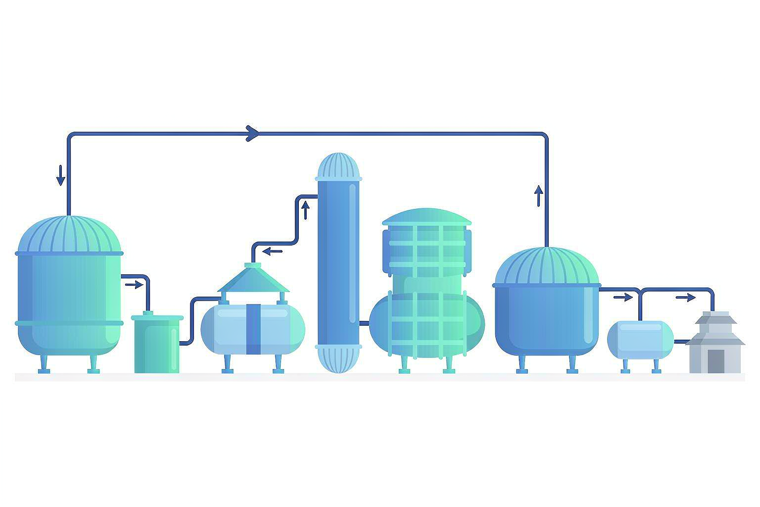
RO "squeezes" salt into the concentrate stream, and concentrate disposal determines the ceiling of the recovery rate — it is also the key to zero liquid discharge. Five pathways:
- ① Direct Reuse (Most Economical): Concentrate is reused for desulfurization, coal yard spraying, slag flushing, and slag washing — in a zinc smelting case, <15% volume of concentrate was reused for slag washing without separate disposal.
- ② DTRO Further Concentration: Disc-tube high-pressure RO pushes concentrate TDS to >80000 mg/L before evaporation, substantially reducing evaporation volume (the three-stage DTRO for desulfurization wastewater follows this approach).
- ③ Evaporation Crystallization (MVR / Multi-Effect): Final brine can be reduced to <5% (desulfurization case), yielding industrial salt; the cost is energy consumption of 8–12 kWh/m³, which constitutes the major expense of ZLD.
- ④ Salt Fractionation Crystallization: NF first separates monovalent (NaCl) from divalent (Na₂SO₄) salts, followed by separate evaporation to obtain industrial salt with purity >98% (GB/T 6009—2014), avoiding mixed salt being disposed of as hazardous waste (at 2000–3000 元 per ton).
- ⑤ Electrodialysis ED / EDR Volume Reduction: Electrically driven membrane separation with energy consumption of approximately 1/3 of RO (8–10 元 per ton of water), suitable for high-salinity wastewater, complementing rather than replacing RO.
6. Process Selection: RO's Position in the Membrane Family
| Process | Rejection Target | Driving Force | Typical Pressure | Salt Rejection | Primary Application |
|---|---|---|---|---|---|
| UF / MF | Suspended solids, colloids, macromolecules (>0.01 μm) | Pressure differential | 0.1–0.3 MPa | No desalination | RO pretreatment |
| NF | Divalent/multivalent ions, partial monovalent | Pressure differential | 0.5–1.5 MPa | Partial 40–90% | Softening, salt fractionation pre-split |
| RO | All dissolved salts, small-molecule organics | Pressure differential | 1.0–8.4 MPa | ≥98% | Desalination and reuse, upstream of ZLD |
| ED / BMED | Ions (electric-field driven) | DC electric field | Low pressure | Desalination/concentration | Desalination + salt recovery |
| MD | All dissolved salts (vapor pressure differential) | Temperature differential | Low-grade heat | >99% | High-salinity, ZLD |
7. 5 Practical Truths You Must Watch in Engineering
- If Pretreatment Fails, RO Will Die — SDI, residual chlorine, oil, and silica are four hurdles. Cutting corners on pretreatment means cutting membrane life short.
- Higher Recovery Rate Is Not Always Better: For every increment, scaling on the concentrate side (CaCO₃ / CaSO₄ / silica) and CIP frequency surge sharply. You must find the "fouling-scaling inflection point."
- Salt Accumulation Is the Ceiling for Reuse: The higher the reuse rate, the higher the salt concentration in the circulating system. Eventually, you must confront the concentrate — particularly prominent in printing and dyeing industrial parks. Salt separation and crystallization are the way forward.
- Membrane Life Is 3–5 年 Years; Replacement Is a Hidden Cost: Anti-fouling membranes + regular CIP can extend life by 25%–30%%, saving more money in the long run than frequent membrane replacement.
- RO Only Removes Salt, It Does Not Degrade COD: Before entering RO, biological/oxidation treatment must reduce COD to an acceptable range (for wastewater reuse, it is recommended that COD < 30 mg/L before entering anti-fouling membranes); otherwise, organic fouling + frequent CIP will cripple operating costs.
References (Genuine Sources)
- Ullah M.N., Mushtaq M.U., Adil S., et al. Application of UF and RO for power plant's wastewater treatment and recycling for environmental sustainability. Journal of Water and Climate Change, 2023, 14(6):1991-2006 (DOI 10.2166/wcc.2023.071).
- Ocal Z.B., Karagunduz A., Keskinler B., Dizge N., Ashqar H.I. Investigation of reusability of effluents from an organized industrial zone wastewater treatment plant using a pressure-driven membrane process. Water Reuse, 2023, 13(4):559-570 (IWA Publishing).
- Lin P.H., Lee P.H., Kin E.K. Integration of Membrane Bioreactor and Reverse Osmosis for Textile Wastewater Treatment and Reclamation: A Pilot-Scale Study. Proceedings of Engineering and Technology Innovation, 2023, 25:01-10 (DOI 10.46604/peti.2023.5273).
- Xia Chuan et al. (CINF Engineering). Two-Stage RO Concentration and Reuse of Zinc Smelting Wastewater. Reported in Industrial Water Treatment; Water Management Insights, 2026-04-25.
- Treatment and Near-Zero Liquid Discharge Process for Gallium Arsenide Wafer Processing Wastewater. Wastewater Treatment Engineering Network dowater.com, 2026-04-29.
- Zero Liquid Discharge of Desulfurization Wastewater from Thermal Power Plants: Three-Stage Pressure Grading with High-Pressure Reverse Osmosis. Changhai Environmental Protection Solutions Station changhaihuanbao.com (field-tested in the 2024–2026 project).
- Advanced Treatment and Reuse Project for Printing and Dyeing Wastewater (Keqiao Case). Project page of Wuxi Mier Environmental Protection wxmier.com.
- TORAY Membrane Specification Guide for EPC Companies (brackish water RO salt rejection 99.3–99.8%, seawater 99.8–99.86%, SDI≤5). jaywater.com.
- Reverse Osmosis: Membranes, Fouling and Maintenance (brackish water RO 10–25 bar, seawater 55–70 bar, design flux, SDI<3–5). fabrico.io.
- Reverse Osmosis Equipment Model Parameter Specifications (brackish water membrane 1.0–1.6 MPa, seawater membrane 5.5–8.4 MPa). di-water.cn.
- GB/T 19923—2005 "The Reuse of Urban Recycling Water — Water Quality Standard for Industrial Uses"; FZ/T 01107—2011 "Water Quality Standard for Reuse in Textile Dyeing and Finishing Industry"; GB/T 6009—2014 "Anhydrous Sodium Sulfate for Industrial Use"; HJ 471—2020 "Technical Specifications for Treatment Engineering of Wastewater from Textile Dyeing and Finishing Industry".
- ROTEC. Semiconductor Desalination Pilot, EMEA (Flow-Reversal RO FR-RO recovery rate 88%–94%). rotec-water.com, 2023.