



 Across multiple industries nationwide (deep treatment of reclaimed water from pr
 Pilot-scale to engineering-scale (tens to thousands of L/d, mostly in advanced t
Photocatalytic Oxidation (Semiconductor Photocatalysis): Using a "Photo-Generated ·OH Network" to Tackle Refractory Organics That Biological Methods Cannot Degrade
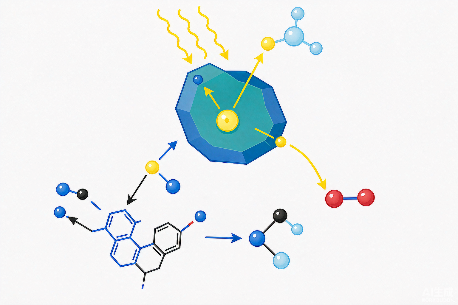
No matter how robust biological treatment is, it often hits a wall against "stable and toxic" organics such as azo dyes in printing and dyeing wastewater, antibiotics in pharmaceutical wastewater, and lignin chlorides in papermaking effluent. Photocatalytic oxidation (typified by TiO₂) uses photons to generate hydroxyl radicals (·OH) and superoxide radicals (·O₂⁻) in situ on the catalyst surface, mineralizing these recalcitrant molecules all the way to CO₂, water, and inorganic salts—and as long as light and catalyst are present, it consumes almost no external chemicals. Drawing on multiple peer-reviewed studies and pilot/solar demonstration data, this article lays out in one go the mechanisms, operating windows, real-world cost accounting, modification pathways, and engineering realities.
1. Principles: Photogenerated Electron-Hole Pairs + ·OH Oxidation
TiO₂ is a wide-bandgap semiconductor; the anatase phase has a bandgap of approximately 3.2 eV, and only photons with energy above this level (wavelength < 387 nm, i.e., near-UV) can excite it. When photons strike TiO₂, valence-band electrons jump to the conduction band, leaving behind holes (h⁺) and forming "electron-hole pairs." The catch is that these charge carriers have lifetimes on the order of nanoseconds, and most recombine within the bulk phase—this is the number-one reason photocatalytic efficiency struggles to climb. Only the minority of carriers that "escape" to the surface do the work: h⁺ directly oxidizes adsorbed organics or oxidizes surface-adsorbed water/OH⁻ into ·OH; electrons reduce adsorbed oxygen into ·O₂⁻. Among these, ·OH is the primary oxidant, with a standard oxidation potential of approximately 2.7–2.8 V, sufficient to indiscriminately cleave most organic bonds.
To improve the "escape rate," there are two engineering directions: one is doping/composite modification to narrow the bandgap (pulling activation light from UV into the visible range), and the other is constructing heterojunctions to "split" electrons and holes onto different materials, reducing recombination. This directly sets up the modification pathways covered in Section 4 below.
2. Three Core Parameters: Dosage, pH, HRT
The real-world cost data below converges on remarkably consistent windows—this is the baseline for process selection:
① Catalyst dosage—0.5–2.5 g/L is the economical range
Pekakis found with real printing and dyeing wastewater that removal efficiency rises rapidly as TiO₂ increases to 0.5 g/L, then "plateaus"—because particles block light penetration, and adding more is simply wasted. N-doped TiO₂ treatment of papermaking wastewater reported in China Pulp & Paper 2021 achieved color removal of 90.2% and CODCr removal of 80.1% at 2.5 g/L, 60 min. Dosage is not a case of "the more the better"—it is constrained by light penetration.
② pH—slightly acidic is better, but not extreme
For printing and dyeing wastewater, UV/TiO₂ is optimal at pH 3 (with H₂O₂ addition providing further enhancement); sol-gel nano-TiO₂ treating printing and dyeing wastewater is optimal at pH 6.0; TiO₂/g-C₃N₄ composite treating tannery wastewater is optimal at pH 5. "Slightly acidic" is the trend, but different systems fall within a range spanning less than an order of magnitude—it cannot be dogmatically written as "must be pH 3."
③ HRT / illumination time—typically 1–4 h for suspended systems
Membrane-coupled photocatalysis (MPR) achieved decolorization of 82–100% at an HRT of 4 h; penicillin wastewater achieved TOC removal of 45.5% in 2 h; nano-TiO₂ treatment of printing and dyeing wastewater achieved COD removal of 95.9% in 3 h. Longer times give higher removal, but with diminishing marginal returns and rising energy consumption.
3. Real-World Engineering / Pilot-Scale Track Record (All from Public Literature and Demonstration Facilities)
| Industry / Scale | Process & Key Operating Conditions | Effluent / Removal Performance | Source |
|---|---|---|---|
| Actual printing and dyeing wastewater / lab-pilot scale | UV-A TiO₂ suspension, 0.5 g/L, pH 3 + H₂O₂, 4 h | Complete decolorization; COD removal 40–90% (depending on conditions); catalyst activity maintained over 3 reuses; acute toxicity to luminescent bacteria completely eliminated | Pekakis et al., Water Research 2006 (doi:10.1016/j.watres.2006.01.019) |
| Simulated printing and dyeing wastewater / solar pilot scale | TiO₂ P-25 + H₂O₂, cumulative energy 50 kJ/L (Plataforma Solar de Almería, Spain) | DOC reduction 70% (cotton); near-complete decolorization; ~54% mineralization for nylon wastewater | Kositzi et al., Solar Energy 2004 |
| Reactive Black 5 dye / membrane-coupled photocatalysis | PTFE membrane + TiO₂ slurry (MPR), HRT 4 h | Decolorization 82–100%, TOC 45–93%, COD 50–85% (depending on initial concentration) | Chem. Eng. J. / Sep. Purif. Technol. 2010 |
| Papermaking wastewater / lab scale | N-doped TiO₂ nanotube arrays, 2.5 g/L, irradiation 60 min | Color removal 90.2%, CODCr 80.1% (only 58.2%/52.2% with plain TiO₂); bandgap 2.98 eV enabling visible-light activation | China Pulp & Paper 2021, 40(3) |
| Actual tannery wastewater / lab scale | TiO₂/g-C₃N₄ (80%) composite, UV 180 min, pH 5, H₂O₂ 0.8 g/L, flow rate 3 L/h | Phenol 93.06%, COD 85.62%, color 80.23% (72.39/68.95/65.80% with pure TiO₂); apparent rate constant 2.09 × higher | Environ. Nanotech. Monit. Manag. 2018 |
| Penicillin production wastewater / lab scale | TiO₂ (P25) powder 500 mg/L, 2 h, pH 3, 35 W, aeration 0.4 L/min | TOC 107.3→59.6 mg/L (45.5%); COD 389.6→217.0 (44.3%); color 156→78 (50.0%) | Technology of Water Treatment 2014, 40(3):98-102 |
| Persistent chlorinated industrial wastewater / SOLARDETOX solar demonstration plant | 2 m³ batches, 100 m² CPC collector aperture, TiO₂ aerated suspension, solar-driven | Validated with dichloroacetic acid/cyanide model compounds; HIDROCEN Madrid 1000 L unit treats recalcitrant chlorinated pollutants | Blanco et al., Solar Energy 2001 |
| Phenolic / neonicotinoid pesticide wastewater / solar CPC pilot scale | Sol-gel ZnO 200 mg/L, 4 h sunlight exposure (Q_UV≈25 kJ/L) | Phenol 89%, imidacloprid 92% (initial 5 mg/L) | Catalysis Today 2022 |
| Ciprofloxacin wastewater / lab scale | BiOBr/biochar/g-C₃N₄ ternary heterojunction, visible light | CIP degradation 94.89% (only 26.63% with pure g-C₃N₄), rate 9 × faster; 60 min TOC mineralization 57.42%, stable over 5 cycles | Surfaces and Interfaces 2025 (doi:10.1016/j.surfin.2025.108045) |
4. Modification Directions: From UV-TiO₂ to Visible-Light Photocatalysis
Pure TiO₂ can only utilize UV light, which accounts for only <5% of sunlight — this is its inherent limitation of "depending on the sun (or lamps)." Two mainstream solutions exist:
- Ion / Non-metal Doping: For instance, N-doping compresses the bandgap from 3.18 eV to 2.98 eV, enabling nanotube arrays to be activated by visible light. China Pulp & Paper 2021 reported that its treatment of papermaking wastewater achieved CODCr removal of 80.1%, while ordinary TiO₂ reached only 52.2%, confirming the tangible gains brought by "visible-light activation."
- Heterojunction Composites: Coupling TiO₂ or g-C₃N₄ with BiOBr, biochar, etc., forms S-scheme charge transfer channels, which both broaden light absorption and suppress charge recombination. The BiOBr/biochar/g-C₃N₄ ternary heterojunction reported in 2025 年 Surfaces and Interfaces achieved 94.89% degradation of ciprofloxacin under visible light (pure g-C₃N₄ only 26.63%), with a rate 9 times faster and stability over 5 cycles; the TiO₂/g-C₃N₄ (80%) composite on tannery wastewater also showed COD removal approximately 17 percentage points higher than pure TiO₂ (85.62% vs 68.95%).
5. Engineering Realities: Photocatalysis Is Not a "Universal Mineralizer"
1. It Is Only Suitable for "Clean Water"
Light must penetrate, making photocatalysis extremely sensitive to turbidity, suspended solids, and color. It is essentially a "polishing" unit for advanced treatment/reuse, and must be placed after biological treatment + filtration — it can never be used as primary treatment to tackle high-concentration raw water.
2. Catalyst Recovery Is a Dilemma
Suspended slurry systems offer high specific surface area and fast kinetics, but nanoparticles are difficult to separate; immobilized/supported membranes are easy to recover but sacrifice active area and mass transfer. Membrane-coupled photocatalysis (MPR, with PTFE membranes retaining TiO₂) is a balanced approach, but introduces membrane fouling and additional energy consumption. On penicillin wastewater, powdered P25 (2 h) achieved TOC removal of 45.5%, far higher than supported membranes (4 coatings, 1.5 h only 24.2%), at the cost of difficult powder recovery.
3. Scale-Up Relies on "Spreading Out the Illuminated Surface"
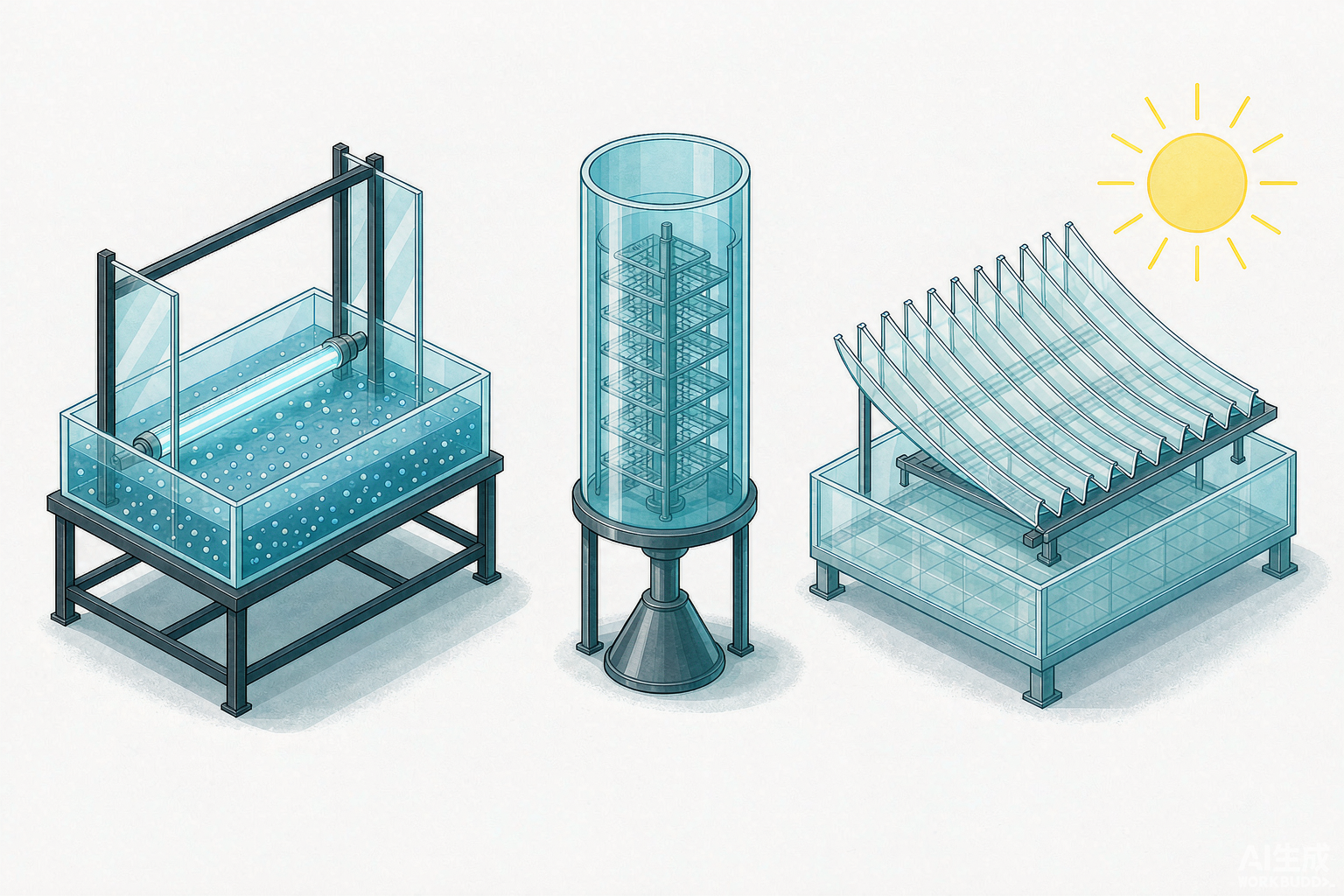
Photon penetration depth is limited, so reactors cannot be deep. The main industrial route is solar CPC (compound parabolic collector) arrays — requiring no tracking and capturing diffuse radiation, with efficiency 30–200% higher than parabolic trough reactors (PTR). SOLARDETOX and HIDROCEN have built 100 m²-scale, thousand-liter demonstration plants treating refractory chlorinated compounds and papermaking wastewater.
4. Don't Be Misled by Literature "Mineralization Rates"
5. Compared with Photo-Fenton, Which Is Faster?
Using both light and oxidants, photo-Fenton (UV/Fe/H₂O₂) can achieve mineralization of up to 90% at a cumulative energy of 50 kJ/L, significantly faster than TiO₂/H₂O₂ at 70% (Kositzi 2004). Photocatalysis wins on "no iron reagent addition, no iron sludge production, and loose pH constraints," but is slower and requires catalyst recovery — the two are complementary rather than substitutive.
6. Photocatalysis vs Other AOPs: Process Positioning
| Process | Oxidant / Mechanism | Chemical Dosing | Light Required | Applicable Water Quality | Typical Removal | Key Limitations |
|---|---|---|---|---|---|---|
| Photocatalytic Oxidation (UV/TiO₂) | Photogenerated ·OH / ·O₂⁻, no chemicals | No (H₂O₂ optional for enhancement) | Yes (mainly UV) | Clean, low turbidity, low-concentration refractory | Color ~100%, COD 40–90% | Limited light penetration, catalyst recovery, relatively slow kinetics |
| Fenton (Fe²⁺/H₂O₂) | ·OH (Fe²⁺ catalyzes H₂O₂) | Yes | No | Acidic pH 3, medium-to-high concentration | COD 50–90% | Iron sludge, narrow pH range, salt generation |
| Catalytic Ozonation | ·OH (catalyst + O₃) | No (H₂O₂ optional) | No | Medium-to-low concentration; bromate control needed for bromide-bearing water | COD 60–90% | O₃/power consumption, byproducts |
| Electro-Fenton | In-situ H₂O₂ + ·OH generation | No (electrolytic generation) | No | Medium-to-low concentration | COD 80%+ | Electrode/energy consumption |
| Photo-Fenton (UV/Fe/H₂O₂) | Light-assisted ·OH | Yes | Yes | Acidic, low turbidity | Fastest mineralization (90% @ 50 kJ/L) | Iron sludge, pH, chemicals |

7. One-Sentence Selection Recommendations
Suitable for: Low-volume wastewater with relatively clean water quality (already biologically treated/filtered), containing low-concentration refractory compounds that resist biodegradation and require mineralization—such as the pretreatment stage of printing and dyeing decolorization and reuse, trace organic contaminants in pharmaceutical/pesticide wastewater, and advanced treatment of paper mill bleaching wastewater; particularly cost-advantageous when solar energy resources are available.
Not suitable for: Primary treatment of high-turbidity, high-suspended solids, high-salinity, or high-volume wastewater; or applications requiring "fast and inexpensive" solutions—in such cases, photo-Fenton or catalytic ozonation is often more practical. Only when positioned as the "final polishing" step in the treatment train can its strengths of "no chemical addition, near-complete decolorization, and toxicity reduction" be fully realized.
References (Authentic Sources)
- Pekakis P A, Xekoukoulotakis N P, Mantzavinos D. Treatment of textile dyehouse wastewater by TiO₂ photocatalysis. Water Research, 2006, 40(6):1276-1286 (doi:10.1016/j.watres.2006.01.019).
- Kositzi M, Antoniadis A, Poulios I, et al. Solar photocatalytic treatment of simulated dyestuff effluents. Solar Energy, 2004, 77(4):591-600.
- Membrane photocatalytic reactor (MPR): PTFE membrane + TiO₂ slurry for Reactive Black 5; 82–100% color, 45–93% TOC, 50–85% COD at HRT 4 h. Chemical Engineering Journal / Separation and Purification Technology, 2010 (doi:10.1016/j.seppur.2010.06.011 类同研究).
- Quan Yulian, et al. N-doped TiO₂ nanotube array membrane photocatalyst and its application in advanced treatment of papermaking wastewater. China Pulp & Paper, 2021, 40(3):106-110.
- Impact of TiO₂ and TiO₂/g-C₃N₄ Nanocomposite to Treat Industrial (tannery) Wastewater. Environmental Nanotechnology, Monitoring & Management, 2018, 10:280-286.
- Zheng Xianjun, Jiang Qiaojuan, Wei Lifang, et al. Study on photocatalytic degradation of printing and dyeing wastewater by nano-TiO₂. Environmental Science.
- Photocatalytic degradation of penicillin production wastewater by TiO₂. Water Treatment Technology, 2014, 40(3):98-102.
- Blanco J, Malato S, et al. New large solar photocatalytic plant: set-up and preliminary results (SOLARDETOX). Solar Energy, 2001, 71(4):287-295.
- Novel ZnO photocatalysts for pollutants' abatement under solar radiation at pilot plant scale (CPC). Catalysis Today, 2022 (doi:10.1016/j.cattod.2022.11.008).
- Hoang N T T, Tran A T K. Enhanced degradation of dyes in secondary textile wastewater: Continuous-flow photoreactors using TiO₂/chitosan/glycerol under UVA. Water Science and Engineering, 2025, 18(4):496-505.
- BiOBr/Biochar/g-C₃N₄ ternary s-scheme heterojunction for visible-light photocatalytic degradation of ciprofloxacin. Surfaces and Interfaces, 2025 (doi:10.1016/j.surfin.2025.108045).
- Lucas M S, Mosteo R, Maldonado M I, et al. Solar Photochemical Treatment of Winery Wastewater in a CPC Reactor. Journal of Agricultural and Food Chemistry, 2009, 57(23):11242-11248.