


 Across multiple industries nationwide (chemical / power plant desulfurization /
  Pilot-scale to engineering-scale (tens to hundreds of m³/d; the largest publicly
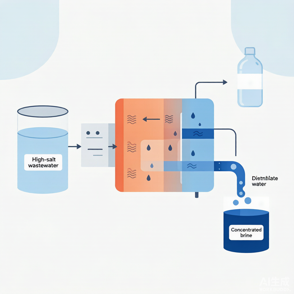
Membrane Distillation (MD): Using a Hydrophobic Membrane That "Fears Water but Not Vapor" to Distill Pure Water from High-Salinity Wastewater
Reverse Osmosis "stalls" in the face of high salinity (osmotic pressure ceiling), and Multi-Effect Evaporation "devours electricity" (100 ℃ plus staggering steam energy consumption). Membrane Distillation, however, relies solely on the water vapor pressure difference across a hydrophobic microporous membrane—driven by low-grade waste heat of 40–80 ℃, with virtually no upper salinity limit. This article draws on peer-reviewed journals and real-world engineering cost ledgers to clarify the mechanisms, parameter windows, salinity tolerance ceilings, and engineering limitations in one go.
1. Principles: Hydrophobic Membrane + Vapor Pressure Difference—Four Configurations, Each with Its Strengths
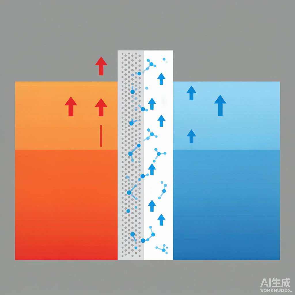
The core logic of MD in one sentence: "Temperature difference creates vapor pressure difference." The higher the feed temperature on the hot side, the greater its saturated vapor pressure; the colder or more vacuumed the cold side, the greater the transmembrane pressure difference, and the more water "evaporates" toward that side, condensing on the cold side to yield pure water. Since it does not depend on osmotic pressure, feed salinity has virtually no effect on "whether separation is possible"—it only affects "how fast separation proceeds." This gives rise to four configurations:
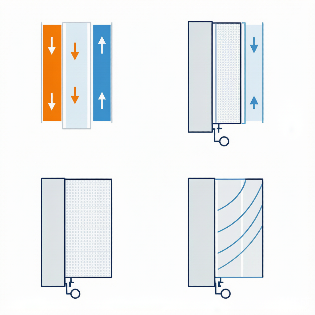
- DCMD (Direct Contact MD): The cold side is directly in contact with a coolant (typically cooling water). Simple structure and relatively high flux, but significant conductive heat loss between hot and cold streams. In pharmaceutical wastewater treatment, DCMD (Desalination 2024) using PTFE membranes achieved approximately 7 L MH with rejection >99%, outperforming PVDF and PP membranes under identical conditions.
- AGMD (Air Gap MD): A stagnant air gap is interposed on the cold side before the condensation plate. Low heat loss, and the permeate can be directly collected—suitable for applications requiring direct water production. When CNNC 404 treated high-salinity low-level radioactive wastewater, AGMD achieved a distillate decontamination factor >10³ at hot-side 65 ℃/cold-side 20 ℃ temperatures and a flow rate of 2 m³/h.
- VMD (Vacuum MD): A vacuum is applied on the permeate side, yielding the highest flux and weakest temperature polarization—making it the mainstream choice for engineering concentration. Mericq et al. treated RO seawater brine concentrate (50 ℃, permeate side 6000 Pa, feed 64–300 g/L) using VMD, achieving a flux of 7–17 L/(m²·h) and a volume reduction of 81.9%.
- SGMD (Sweeping Gas MD): An inert gas sweeps the permeate side to carry away and condense the vapor. Suitable for volatile product recovery, but with the lowest flux.
Two "polarization" effects demand close attention: Temperature Polarization (TP)—the membrane surface is cooler than the bulk feed, shrinking the effective temperature difference; and Concentration Polarization (CP)—the membrane surface salinity is higher than the bulk, suppressing the water vapor partial pressure. Both weaken the driving force and are mitigated by increasing flow velocity (inducing turbulence). This is also why VMD, with no liquid phase on the vacuum side and the weakest temperature polarization, is often the preferred choice in engineering applications.
2. Key Operating Parameter Windows
Extensive single-factor and pilot-scale experiments have clearly mapped out the "operating roadmap" for MD. Below is a practical range synthesized from peer-reviewed experiments:
- Feed Temperature: 40–80 ℃ is the mainstream range. Flux shows a near-exponential positive correlation with temperature (Petrochemical Institute single-factor experiment achieved 4.21 L/(m²·h) at 70 ℃; Xing et al. observed flux increase from 3.95 to 6.12 L/(m²·h) as temperature rose from 75 to 90 ℃). However, hotter is not always better — CNNC 404 found that above 65 ℃, the flux growth rate slows and rejection rate slightly decreases; above 80 ℃, membrane aging and energy consumption must also be weighed.
- Vacuum Degree (VMD): The lower the absolute pressure on the permeate side, the higher the flux (Petrochemical Institute: 0.6→0.98 atm yields 0.19→4.21 L/(m²·h)), and a critical value exists (≈ atmospheric pressure − feed saturated vapor pressure); flux only "takes off" below this critical point.
- Flow Rate: In the laminar region, flux shows a near-linear positive correlation (Petrochemical Institute: 10.5→41.8 L/h yields 2.90→3.97), then plateaus after turbulence; it also weakens the boundary layer and reduces CP/TP.
- Salt Concentration: The saltier the feed, the lower the flux — but MD has virtually no upper limit for salt tolerance — Petrochemical Institute observed only 26.8% decline for 200 g/L relative to 50 g/L; CNNC 404 reported approximately 1/3 reduction for 320 g/L relative to 10 g/L. In contrast, RO struggles above 7% TDS. This is the fundamental reason MD is written into "Zero Liquid Discharge" roadmaps.
- Membrane Material: PTFE (optimal hydrophobicity/temperature resistance/wetting resistance, porosity up to 82%) > PVDF > PP. In industrial water treatment, 2024 sulfuric acid waste liquor PTFE hollow-fiber VMD operated continuously for 10 天 at 80 ℃/2%/1.0 m/s, with condensate conductivity stable at 11–13 μS/cm (tap water ≈ 200) and separation efficiency of 99.9%.
III. Real Engineering Cost Ledger (All from Public Literature and Engineering Reports)
| Industry / Scale | Process & Key Operating Conditions | Effluent / Performance | Source |
|---|---|---|---|
| High-salinity wastewater from chemical industrial park (RO concentrate) / Full-scale project | OriginWater PTFE/ceramic composite membrane, flux 25 L/(m²·h), service life 3 年; driven by waste heat from 80–120 ℃ reactor in Wanhua Chemical | Desalination rate 99.9% at a chemical industrial park in Jiangsu; Wanhua energy consumption per ton of water 45→8 kWh, annual water savings 300 万 tons; concentrate recovered as industrial-grade sodium sulfate (purity 99.3%, 5 万 tons/year) | Industry reports (2025, commercial source, [to be verified]) |
| Shale gas fracturing flowback fluid (after wet oxidation) / Pilot trial | Liu Yucheng et al., VMD; feed COD 299 mg/L, NaCl 67870 mg/L, 70 ℃, vacuum 0.085 MPa, 90 min | Effluent NaCl only 1.17 mg/L, COD reduced to 93.2 mg/L | whh2o (review by Sinopec Exploration & Production Research Institute) |
| Desulfurization wastewater from power plant / Pilot trial | PTFE multi-effect plate VMD; optimal 75 ℃, feed pressure 0.1 MPa, cooling 20 ℃, feed water 70 L/h, vacuum 0.095 MPa; salt 6%, total hardness ≤550 mg/L | Concentrated to salt mass fraction 20%+, desalination rate >99%, flux >5.5 kg/(m²·h), permeate conductivity <100 μS/cm (meeting GB/T 50050—2017 circulating cooling water make-up) | gturbo.cn engineering validation |
| Pharmaceutical wastewater (high salinity, high boron) / Real water samples | DCMD; comparison of multiple commercial hydrophobic membranes, PTFE membrane optimal | PTFE membrane flux ~7 LMH, rejection >99% (superior to PVDF/PP); Na/K/phosphate/boron removal >99%, meeting discharge standards; volume reduction 30%–40% to incineration; savings of 19%–34% vs. incineration | Desalination, 2024 (Lee Nuang Sim et al.) |
| High-salinity low-level radioactive wastewater / Nuclear power plant full-scale project | VMD/AGMD; Yangjiang Nuclear Power Phase III 200 m³/d, continuous operation; feed salinity 23.5 g/L (mainly NaCl) | Salinity 23.5→<100 mg/L, β 3.2×10⁴→not detected, γ 1.8×10³→<10 Bq/L; annual water savings 7.3 万 tons, recovered industrial salt purity 99.6%, payback period 2.5 年; Wen et al. VMD (80 g/L) decontamination factors for Cs/Sr/Co 6000/3700/8300 | gqhb168 / dowater (commercial source, [to be verified]) |
| Landfill leachate / Two-stage DCMD resource recovery | Stage 1: PP hollow fiber absorbs ammonia with sulfuric acid → ammonium sulfate; Stage 2: PTFE flat-sheet membrane condenses and recovers water | Ammonia recovery rate 87.38%, 1 m³ ammonia recovered per 2.20 kg of leachate; Stage 2 flux 11.7 kg·m⁻²·h⁻¹, color/TOC/NH₃/phosphorus rejection 99.99%/99.98%/99.85%/99.88%, respectively | Desalination, 2024, 574:117110 |
4. Process Comparison: MD vs RO vs Multi-Effect Evaporation
| Dimension | Membrane Distillation (MD) | Reverse Osmosis (RO) | Multi-Effect Evaporation (MEE) |
|---|---|---|---|
| Maximum Salt Tolerance | 25%–30%+ TDS (virtually no upper limit) | Approx. 7% TDS (capped by osmotic pressure) | Unlimited (up to crystallization) |
| Operating Temperature | 40–80 ℃ (low-grade waste heat) | Ambient | 100–120 ℃ |
| Rejection Precision | Non-volatiles >99% (ions/organics/radionuclides) | Desalination 95–99%; boron/silica/small-molecule organics may pass through | Near-complete removal (risk of mist carryover) |
| Energy Characteristics | Low-temperature heat driven; waste heat can be as low as single-digit kWh/t; without waste heat: 8–45 kWh/t | High-pressure pump driven, approx. 2–4 kWh/t (but salt-limited) | Steam driven, typically >200 kWh/t (high) |
| Outputs | High-purity permeate + concentrate that can be further crystallized | High-purity permeate + difficult-to-treat brine | Distillate + crystallized salt |
| Key Limitations | Relatively low flux, membrane wetting, requires heat source | Not tolerant of high salinity; brine difficult to dispose of | High energy consumption, scaling and corrosion |
Positioning in one sentence: RO is the "workhorse for ambient desalination but fears high salinity," MEE "can handle anything but at high energy cost," and MD sits in between — it is the step that "re-concentrates and volume-reduces" RO brine and high-salinity difficult-to-treat wastewater, rather than a standalone "ultimate purification" solution.
V. Engineering Realities That Must Be Watched: 5 Hard Truths
VI. One-Sentence Selection Advice
Suitable for: Industrial wastewater where low-grade waste heat is available (e.g., chemical reaction heat, power plant waste heat, solar energy), where discharge or reuse water quality requirements are high, and where RO struggles due to high salinity. Typical scenarios include concentrated brine from chemical Industrial Parks, desulfurization wastewater from power plants, oil and gas field produced water, and high-salinity pharmaceutical or nuclear-related wastewater.
Not suitable for: General wastewater where cheap heat sources are unavailable, extremely low unit capital investment is required, and salinity is not particularly high. In such cases, RO or evaporation is often more economical. Reserve MD for the niche requirement of "needing high-purity product water while being constrained by high salinity."
References (Genuine Sources)
- Mericq J P, et al. Vacuum membrane distillation of reverse osmosis concentrates (RO seawater concentrate VMD: 50 ℃/6000 Pa/feed 64–300 g/L → flux 7–17 L/(m²·h), volume reduction 81.9%) — cited from whh2o review.
- Liu Yucheng, et al. Vacuum membrane distillation treatment of shale gas fracturing flowback fluid after wet oxidation. Feed COD 299 mg/L, NaCl 67870 mg/L → 70 ℃/0.085 MPa/90 min → NaCl 1.17 mg/L, COD 93.2 mg/L. — whh2o.com.
- VMD treatment of simulated high-salinity wastewater using polypropylene hollow fiber membrane (Sinopec Petroleum Exploration and Production Research Institute). Optimal 0.98 atm/70 ℃/41.8 L/h/35 g/L → 4.21 L/(m²·h); 200 g/L only 26.8% lower than 50 g/L; effluent salinity <10 μg/L. whh2o.com/jishufenxiang363/3200.html.
- gturbo. PTFE multi-effect plate vacuum membrane distillation for power plant desulfurization wastewater. Optimal 75 ℃/0.1 MPa/cooling 20 ℃/70 L/h/vacuum 0.095 MPa; salt 6%/hardness ≤550 → concentrated to 20%+, desalination >99%, flux >5.5 kg/(m²·h), permeate conductivity <100 μS/cm (meeting GB/T 50050—2017). gturbo.cn/sys-nd/351.html.
- Lee Nuang Sim, Jayaraman P, Lau Y H, Chong T H, Wang R. Pharmaceutical wastewater treatment using direct contact membrane distillation. Desalination / ScienceDirect, 2024. PTFE membrane ~7 LMH, rejection >99%; saves 19%–34% compared to incineration.
- Brito F S L, Lebron Y A R, Moravia W G, Lange L C A, Santos M C. Resource recovery from landfill leachate by two-stage of direct contact membrane distillation. Desalination, 2024, 574:117110 (doi:10.1016/j.desal.2023.117110). Ammonia recovery 87.38%, 2.20 kg/m³; second-stage flux 11.7 kg·m⁻²·h⁻¹, color/TOC/NH₃/phosphorus rejection >99.8%.
- ZHANG Liyi, SI Zetian, XIAO Fangmiao, ZHOU Chuan'en. Hollow fiber vacuum membrane distillation of sulfuric acid waste liquid (PTFE). Industrial Water Treatment, 2024, 44(11):93-98. Continuous 10 天 80 ℃/2%/1.0 m/s, condensate conductivity 11–13 μS/cm, separation efficiency 99.9%.
- Second Branch of CNNC 404 Co., Ltd. Air gap membrane distillation treatment of high-salinity low-level radioactive wastewater. dowater.com/jishu/2022-05-11/2495958. Hot 65/cold 20 ℃, flow rate 2 m³/h; 320 g/L flux reduction of approximately 1/3 compared to 10 g/L; decontamination factor >10³ (GB 8978—1996).
- Wen et al. VMD treatment of low-level radioactive wastewater (feed 80 g/L). Cs/Sr/Co decontamination factors 6000/3700/8300. — cited from whh2o review.
- Guangdong Guanqing Environmental Protection / industry report (2025): OriginWater PTFE/ceramic composite membrane 25 L/(m²·h), lifespan 3 年; Wanhua Chemical residual heat treatment energy consumption per ton of water 45→8 kWh, sodium sulfate purity 99.3%; Yangjiang Nuclear Power Phase III 200 m³/d, salt purity 99.6%, payback period 2.5 年 (commercial figures, [to be verified]).