



 Across multiple industries nationwide (petrochemical refining / machining / food
 Pilot-scale to full-scale engineering (from tens to tens of thousands of m³/d)
Dissolved Air Flotation (DAF): Using "Microbubble Grippers" to Lift Oil Droplets and Fine Sludge That Settling Tanks Can't Catch to the Water Surface
Biological methods rely on "consumption," membrane methods rely on "sieving," and sedimentation methods rely on "settling." But pollutants like emulsified oil from refineries, fats and oils from food processing, and fine fibers from papermaking have densities close to or even lighter than water—sedimentation tanks simply cannot make them "settle out." Dissolved Air Flotation (DAF) takes a different approach—it dissolves air into water under pressure, then instantly releases it under reduced pressure to generate 20~50 μm micro-bubbles that act as "grippers" to lift light oils, fine sludge, and flocs to the surface for skimming. Using real-world data from refineries, food processing, and papermaking plants, this article explains its mechanism and four key engineering control parameters in one go.
1. Principle: Henry's Law as the Foundation, Micro-Bubbles as "Grippers"
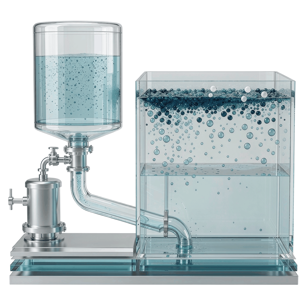
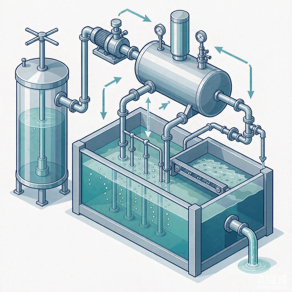
The core of DAF is Henry's Law: the solubility of a gas in a liquid is proportional to the partial pressure of that gas. In practice, a portion of the effluent (typically 10%~30%) is pumped into a saturator vessel by a high-pressure pump, where a large amount of air is dissolved into the water under supersaturation at 0.3~0.6 MPa. This "saturated water" then passes through a specialized release nozzle where it undergoes instantaneous pressure reduction to atmospheric pressure, causing the supersaturated air to rapidly come out of solution and form dense clouds of micro-bubbles (20~50 μm, optimal range 30~40 μm).
The smaller the micro-bubbles, the larger the specific surface area, the slower the rise rate, and the greater the opportunity for collision and adhesion with pollutants. They collide with and adhere to oil droplets, colloids, and flocs in the wastewater, forming "bubble–particle agglomerates" whose overall density is lower than water. These agglomerates therefore float rather than settle, accumulating as a scum layer on the surface that is continuously removed by a skimmer; clarified water is collected from the bottom outlet. The complete process sequence is: Coagulation/Flocculation → Pressurized Dissolution of Air in a Portion of Effluent → Pressure Release via Nozzle to Generate Micro-Bubbles → Contact and Adhesion → Separation and Flotation → Skimming and Effluent Discharge.
A critical engineering point here: coagulation/flocculation is almost always required upstream of flotation. Oil droplets and fine particles typically carry a negative charge (when the ζ potential is below −10 mV, electrostatic repulsion prevents adhesion). Coagulants such as PAC and FeCl₃ are used to neutralize the surface charge to near 0, followed by the addition of long-chain polymers (PAM) to bridge the destabilized particles into flocs of 1~5 mm, which the micro-bubbles can then effectively "grip." Thus, DAF's "micro-bubbles" and upstream "coagulation" work as an integrated system—bubbles alone cannot capture bare particles.
2. Four Key Control Parameters: Saturation Pressure, Recycle Ratio/Gas–Solid Ratio, Surface Loading Rate
DAF selection and operation essentially come down to four parameters, which directly determine "whether it can float, how cleanly it floats, and how much it costs."
① Saturation Pressure: 0.3~0.6 MPa (typical operating range 4~6 bar)
Pressure determines how much air can be dissolved per liter of recycle flow. If the pressure is too low, the bubbles generated are larger and adhesion efficiency drops; if too high, equipment and energy costs rise sharply. Standard ranges cited across multiple engineering manuals are 0.3~0.6 MPa (approximately 4~6 bar), with common design points at 0.4~0.5 MPa. Saturation efficiency (actual dissolved amount/equilibrium solubility) typically ranges from 0.5~0.8, and should be measured on-site during commissioning and acceptance. Many cases of "poor performance" trace back to an undersaturated saturator vessel.
② Recycle Ratio: 20%~30% (range 10%~50%)
The recycle ratio refers to the "volume of pressurized saturated water / total influent flow rate." The common design point is 20%~30%, with the upper limit used for high-suspended-solids wastewater. There is an important engineering trade-off here: using "partial effluent recycle with pressurization" rather than "full-flow influent pressurization" keeps already-flocculated flocs in the atmospheric-pressure zone at all times, preventing them from being sheared apart by pumps and pressure-reducing valves. If the recycle ratio is too low, insufficient bubbles are supplied; if too high, pump energy is wasted.
③ Air-to-Solids Ratio A/S: 0.01~0.04 kg kg air/kg TSS (the most critical chemical parameter)
The air-to-solids ratio = mass of released air / mass of solids to be floated, and it is the true "master control knob" of DAF. Literature consistently reports a typical range of 0.005~0.06, with an optimal range of 0.01~0.04. If too low, solids will not float (high residual TSS); if too high, it only increases energy consumption and tends to generate excessive foam. A published calculation example: for wastewater with 100 m³/h and TSS of 500 mg/L, with a saturation tank pressure of 5 bar, a saturation efficiency of 0.8, and a recycle ratio of 10%, A/S ≈ 0.018, which falls exactly within the target range; if the influent TSS doubles to 1000 mg/L, A/S drops to approximately 0.009 , falling below the lower limit, requiring the recycle ratio to be increased to approximately 20% or the pressure to be raised to compensate for the air supply.
④ Surface Loading Rate: 5~8 m³/(m²·h) (range 3~15)
Surface loading rate = flow rate / flotation tank surface area, and it must be lower than the rise velocity of the "bubble–floc agglomerate" (approximately 10~20 m/h for a microbubble system). If the loading rate is too high, solids are carried out by the flow before reaching the water surface, resulting in solids breakthrough. Conventional DAF systems use 5~8 m³/(m²·h); for high-grease wastewater, the lower limit of 3~4 should be adopted. Regarding retention time, the contact zone requires 1~5 min (for bubble–pollutant attachment), the separation zone requires 10~30 min (for flotation and separation), and total retention is typically 15~40 min.
III. Real-World Engineering Cost Data (all from public sources)
| Wastewater Type / Scale | Key Operating Conditions | Removal / Effluent | Source |
|---|---|---|---|
| Refinery oily wastewater (Example A) | Surface loading 3.4 m³/(m²·h), dissolved air 0.25~0.6 MPa, recycle ratio 20~50%, aluminum salt 50 + polymer 5 mg/L | Inlet oil 220→outlet 10 mg/L, oil removal 95.5% | "Oily Wastewater Treatment and Equipment" Table 7-6 |
| Refinery oily wastewater (Example B) | Surface loading 7.4 m³/(m²·h), aluminum salt 75 + polymer 5 mg/L | Inlet oil 460→outlet 37 mg/L, oil removal 92% | "Oily Wastewater Treatment and Equipment" Table 7-6 |
| Refinery oily wastewater (Example C) | Inlet oil 2000 mg/L, polymer 2~3 mg/L | Outlet oil 100 mg/L, oil removal 95% | "Oily Wastewater Treatment and Equipment" Table 7-6 |
| Refinery/petrochemical saline wastewater (two-stage multiphase dissolved air flotation) | Two-stage multiphase dissolved air, influent oil <100 mg/L | Two-stage effluent oil ≤20 mg/L, removal >80%; SS removal >80%, petroleum removal 96%, COD approx. 30% | Wastewater Treatment Engineering Network (dowater.com, 2023-08) |
| Refinery wastewater DAF pilot test | 200 m³/d, water depth 2 m, HRT 20 min, air-to-liquid ratio 1.0%, microbubbles 50~100 μm | Effluent oil 20 / COD 120 / SS 35 mg/L; oil removal 87%, COD 73%, SS 81%, scum removal >95% | Wanfang "Design and Performance Study of DAF Unit for Deep Oil-Water Separation of Refinery Wastewater" (2026) |
| Petroleum refining enterprise oily wastewater (400 m³/h, two-stage DAF) | Multiphase balanced dissolved air, bubbles <30 μm | Oil removal >95%, SS >80%, effluent petroleum ≤20 / SS ≤40 mg/L; footprint saving 20~40% | Nanjing Zhonghengyuan Environmental Protection (commercial site, [to be verified]) |
| Quick-frozen food wastewater (DAF) | Recycle ratio 20~40%, dissolved air pressure 0.35~0.50 MPa, surface loading 3~6 m³/(m²·h), HRT 15~30 min | SS removal ≥85%, oil & grease ≥95%, reducing load on downstream biological treatment by 30~50%; effluent SS≤70, oil & grease≤15, COD 40~60% | Zoncen Environment wateretechs (commercial site, [to be verified]) |
| Papermaking white water (DAF fiber recovery) | A/S 0.005~0.015, HLR 6~8 m³/(m²·h), aluminum salt or PAC | Fiber recovery >95%, white water clarified and reused | Cheneng / Metcalf & Eddy compilation |
IV. Applicability Boundaries: DAF vs. Gravity Sedimentation vs. Inclined Tube/High-Density Clarification
| Comparison Item | DAF (Dissolved Air Flotation) | Gravity Sedimentation | Inclined Plate / High-Density Clarification |
|---|---|---|---|
| Particles best suited for separation | Low-density oils, emulsified oils, fine fibers, light flocs (those that "won't settle") | High-density inorganic particles (sand, metal hydroxides) | Relatively dense inorganic suspended solids |
| Footprint | Small (approximately 1/4~1/10 of a sedimentation tank) | Large | Small |
| TSS Removal Rate | 90%~98% | 50%~80% | 80%~95% |
| Oil/Grease (FOG) Removal | Excellent (85%~99%) | Poor | Moderate |
| Standalone COD Removal | 30%~70% | 25%~40% | 30%~50% |
| Scum/Sludge Solids Content | 3%~8% (thick, reduces dewatering needs) | 0.5%~2% | 0.8%~2% |
| Capital / O&M Cost | Moderate (requires dissolved air system + chemical dosing) | Low | Low |
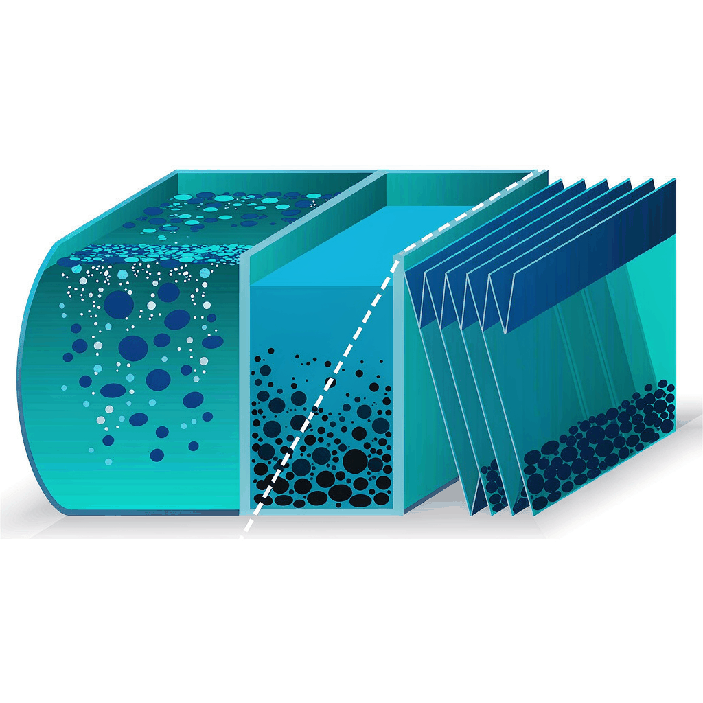
Selection guide: Oil present, fine sludge, tight footprint → choose DAF; for purely dense inorganic particles with ample land and minimal initial investment as the priority, gravity sedimentation or inclined plate clarification is more cost-effective. In engineering practice, DAF often serves as the "gatekeeper" pretreatment for downstream treatment units such as MBR, biological treatment, and filtration — removing FOG and fine SS upfront to protect downstream membranes and microorganisms.
V. Engineering Reality: 5 Constraints That Must Be Watched
VI. One-Sentence Selection Recommendation
Suitable for: Wastewater containing oil/high FOG, fine SS, and fibrous materials (petrochemical refining, machining emulsion, food processing, papermaking, printing and dyeing, slaughterhouses), where footprint is tight and skimmings concentration/volume reduction is desired; also commonly used as pretreatment for MBR/biological treatment/filtration.
Not suitable for: Inorganic wastewater with high density, coarse particles, and little to no oil (gravity sedimentation is more economical); or applications requiring deep removal of soluble COD without downstream biological treatment (DAF alone cannot achieve this).
References (Authentic Sources)
- "Oily Wastewater Treatment and Equipment" (Wastewater Treatment / Water Supply and Drainage textbook), Table 7-6 Application examples of dissolved air flotation in oily wastewater treatment at oil refineries (4 sets of engineering parameters: surface loading rate 3.4~9.8 m³/(m²·h), oil removal 89%~95.5%, dissolved air pressure 0.25~0.6 MPa, recycle ratio 20%~50%).
- Metcalf & Eddy. Wastewater Engineering: Treatment and Resource Recovery. Chapter 2 Solid-Liquid Separation / DAF design parameters (air-to-solids ratio, recycle ratio, surface loading rate, industry Quick-Reference); Cheneng Water compiled DAF design table based on this (HLR 3~8, A/S 0.005~0.06, industry recycle ratios 15%~50%).
- "Standard for Design of Outdoor Wastewater Engineering" GB 50014—2021 (relevant clauses on DAF tank design).
- Wanfang Data. Design and performance study of dissolved air flotation device for deep oil-water separation of refinery wastewater[J]. (periodical liucgy202607033, 2026): 200 m³/d pilot test, HRT 20 min, effluent oil 20/COD 120/SS 35 mg/L, oil removal 87%, COD removal 73%, SS removal 81%.
- Wastewater Treatment Engineering Network. Oil-water separation technology for saline wastewater treatment at oil refineries (2023-08-30): two-stage multi-phase dissolved air flotation, influent oil <100 mg/L, effluent ≤20 mg/L, petroleum substance removal 96%, SS removal >80%.
- Nanjing Zhonghengyuan Environmental Protection. Stable compliance of oily wastewater treatment, dissolved air flotation adds another achievement (commercial website, [to be verified]): 400 m³/h two-stage multi-phase dissolved air flotation, bubble size <30 μm, oil removal >95%, SS removal >80%, effluent petroleum substance ≤20 mg/L.
- Keli'er Technology (SINOKLE). CDFU cyclone dissolved air flotation product documentation (commercial website, [to be verified]): single-stage oil removal >90%, floating oil ≥99%, emulsified oil 80%~90%, bubble size 5~30 μm, Dushanzi Petrochemical 2000 ppm→≤10 ppm case studies, etc.
- Zhongsheng Environmental. DAF treatment solution for quick-frozen food wastewater / grease wastewater DAF+MBR solution (wateretechs.com, commercial website, [to be verified]): SS ≥85%, grease ≥95%, recycle ratio 20~40%, dissolved air pressure 0.35~0.50 MPa, surface loading rate 3~6 m³/(m²·h).
- Reynolds & Bauhm. Dissolved-Air Flotation – Micro-Bubble Technology / DAF design parameters (A/S 0.01~0.05, bubble size 20~50 μm, dissolved air pressure 4~6 bar, recycle ratio 6~30%, surface loading rate 5~15 m/h and calculation examples).
- Zhongsheng Environmental / Hydropure. DAF 2025–2026 engineering specifications (dissolved air pressure 3~6 bar, A/S 0.005~0.060, micro-bubbles 20~80 μm, HLR 5~15, TSS 80~99%, FOG 85~99%, energy consumption 0.1~0.3 kWh/m³).
- GB 8978—1996 "Integrated Wastewater Discharge Standard" (petroleum substance: Class I 5 / Class II 10 / Class III 20 mg/L, used as compliance reference for DAF effluent from oily wastewater treatment).